Noncontact Electric Power Transmission System

a transmission system and non-contact technology, applied in electromagnetic wave systems, transformers, inductances, etc., can solve the problems of inability to use without modification, inability to obtain stable output characteristics, and high probability of deterioration of transmission efficiency, so as to achieve optimal transmission efficiency and reduce design time

Active Publication Date: 2010-09-02
MURATA MFG CO LTD
View PDF4 Cites 210 Cited by
  • Summary
  • Abstract
  • Description
  • Claims
  • Application Information

AI Technical Summary

Benefits of technology

[0011]As above, in the present invention, a relationship between respective ones of the oscillating frequency (Fosc) of the control IC, the resonant frequency (Fpr) of the LC series resonant circuit or the LC parallel resonant circuit in the power transmitter circuit section, and the resonant frequency (Fsr) of the LC parallel resonant circuit in the power receiver circuit section, is set as follows: Fpr<Fosc<Fsr. This makes it possible to obtain optimum transmission efficiency in the noncontact electric power transmission system, and reduce a design time therefor.

Problems solved by technology

This characteristic cannot be used without modification, because it is unfit for an output necessary as a commonly-used power supply.
Moreover, if one of the three frequencies deviates from the resonance point, the output voltage will sharply drop and become unstable, which makes it impossible to obtain a stable output characteristic.
If the two frequencies are adjusted in an imbalanced manner, transmission efficiency is likely to deteriorate.
Furthermore, a design process becomes complicated and requires a lot of time.

Method used


Image

  • Noncontact Electric Power Transmission System
  • Noncontact Electric Power Transmission System
  • Noncontact Electric Power Transmission System

Examples


Embodiment Construction

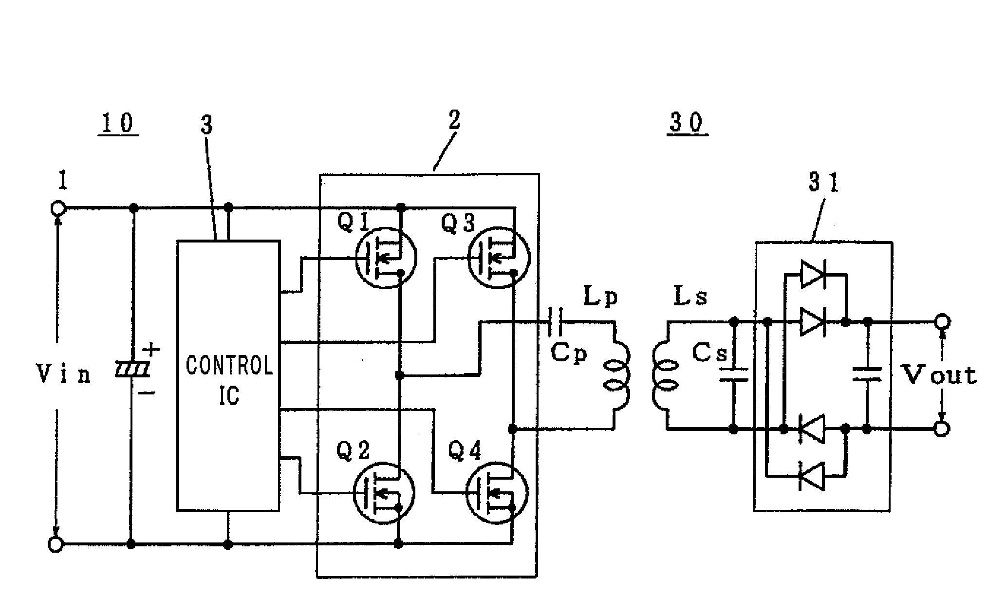
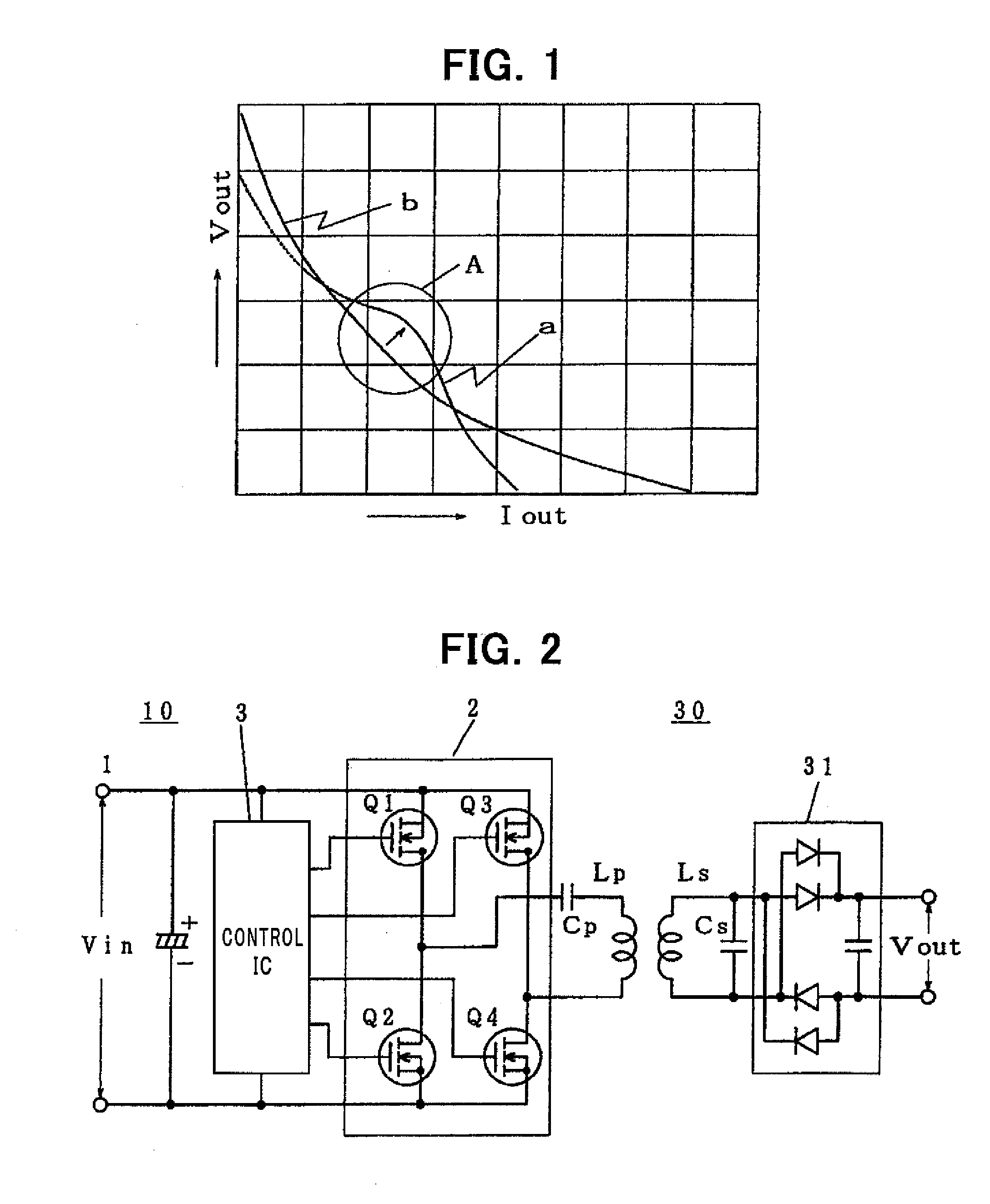
[0018]The present invention is directed to a noncontact electric power transmission system having a power transmitter circuit section and a power receiver circuit section which are adapted to be coupled to transmit electric power from a transmitter coil provided in the power transmitter circuit section to a receiver coil provided in the power receiver circuit section, in a noncontact manner by means of electromagnetic induction. The noncontact electric power transmission system comprises: a separately-excited or self-excited switching circuit provided in the power transmitter circuit section; a control IC operable to drive the switching circuit; an LC series resonant circuit including a capacitor connected in series to the transmitter coil or an LC parallel resonant circuit including a capacitor connected in parallel to the transmitter coil; and an LC parallel resonant circuit including a capacitor connected in parallel to the receiver coil, wherein an oscillating frequency (Fosc) o...


PUM


Abstract

Disclosed is a noncontact electric power transmission system having a power transmitter circuit section 10 and a power receiver circuit section 30 which are adapted to be coupled to transmit electric power from a transmitter coil Lp provided in the power transmitter circuit section 10 to a receiver coil Ls provided in the power receiver circuit section 30, in a noncontact manner by means of electromagnetic induction. The noncontact electric power transmission system comprises: a separately-excited or self-excited switching circuit 2 provided in the power transmitter circuit section 10; a control IC 3 operable to drive the switching circuit 2; an LC series resonant circuit including a capacitor Cp connected in series to the transmitter coil Lp or an LC parallel resonant circuit including a capacitor Cp connected in parallel to the transmitter coil Lp; and an LC parallel resonant circuit including a capacitor Cs connected in parallel to the receiver coil Ls, wherein an oscillating frequency (Fosc) of the control IC 3, a resonant frequency (Fpr) of the LC series resonant circuit or the LC parallel resonant circuit in the power transmitter circuit section 10, and a resonant frequency (Fsr) of the LC parallel resonant circuit in the power receiver circuit section 30, have the following relationship: Fpr<Fosc<Fsr.

Description

BACKGROUND OF THE INVENTION[0001]1. Field of the Invention[0002]The present invention relates to a noncontact electric power transmission system, and more specifically to a design technique of, in a noncontact electric power transmission system comprising a power transmitter circuit section and a power receiver circuit section, clarifying a relationship between respective ones of a switching oscillating frequency in the power transmitter circuit section, an LC resonant frequency in the power transmitter circuit section, and an LC resonant frequency in the power receiver circuit section, to facilitate obtaining required characteristics.[0003]2. Description of the Related Art[0004]Heretofore, a resonant full-bridge system has been generally used in a type of noncontact electric power transmission system designed to achieve high efficiency in a contactless manner under a low DC input power.[0005]In the resonant full-bridge system, a switching circuit is driven by an oscillating frequen...

Claims


Application Information

Patent Timeline
Patent Type & Authority Applications(United States)
IPC IPC(8): H02J17/00H02M3/28
CPCH02J5/005Y02B70/1433H02M3/337Y02B70/10H02J50/12H02M3/33573H02M3/01
Inventor KOJIMA, HIDEKI
Owner MURATA MFG CO LTD
Why Eureka
Try Eureka