Motor

Inactive Publication Date: 2010-09-02
SUMIDA CORP
View PDF11 Cites 4 Cited by
  • Summary
  • Abstract
  • Description
  • Claims
  • Application Information

AI Technical Summary

Benefits of technology

[0025]According to the above-described invention, even if a reduction gear comprising a planetary gear is provided, the original rotation angle of the rotor of the motor can be detected by the rotation angle detection sensor, so that fine rectification control can be performed.
[0026]Also, because the rotation angle of the rotor of the motor is detected by the conductor pattern and the rotation angle detection sensor provided opposing the conductor pattern, it is not necessary to provide rotation angle detection sensors throughout the whole circumference 360° of the rotor, so

Problems solved by technology

In contrast, in a brushless motor having a reduction gear, because the original number of revolutions of the motor and the number of revolutions of the rotation axis of the moto

Method used


Image

  • Motor
  • Motor
  • Motor

Examples


Example

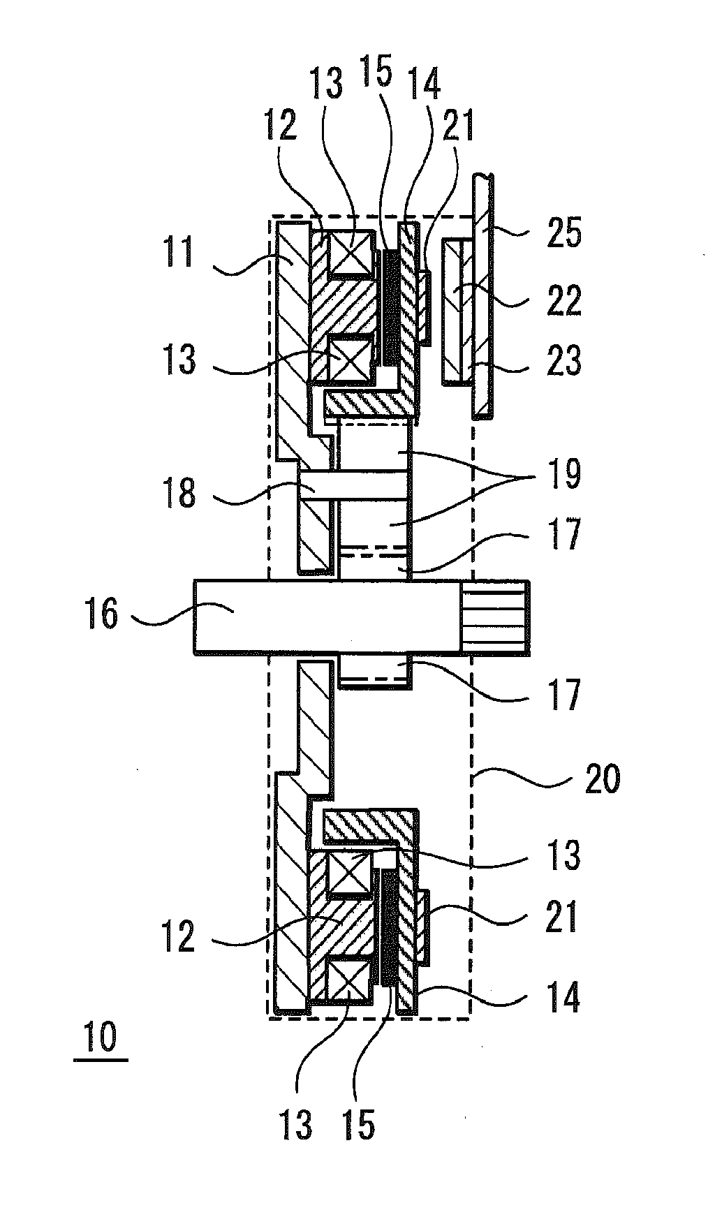
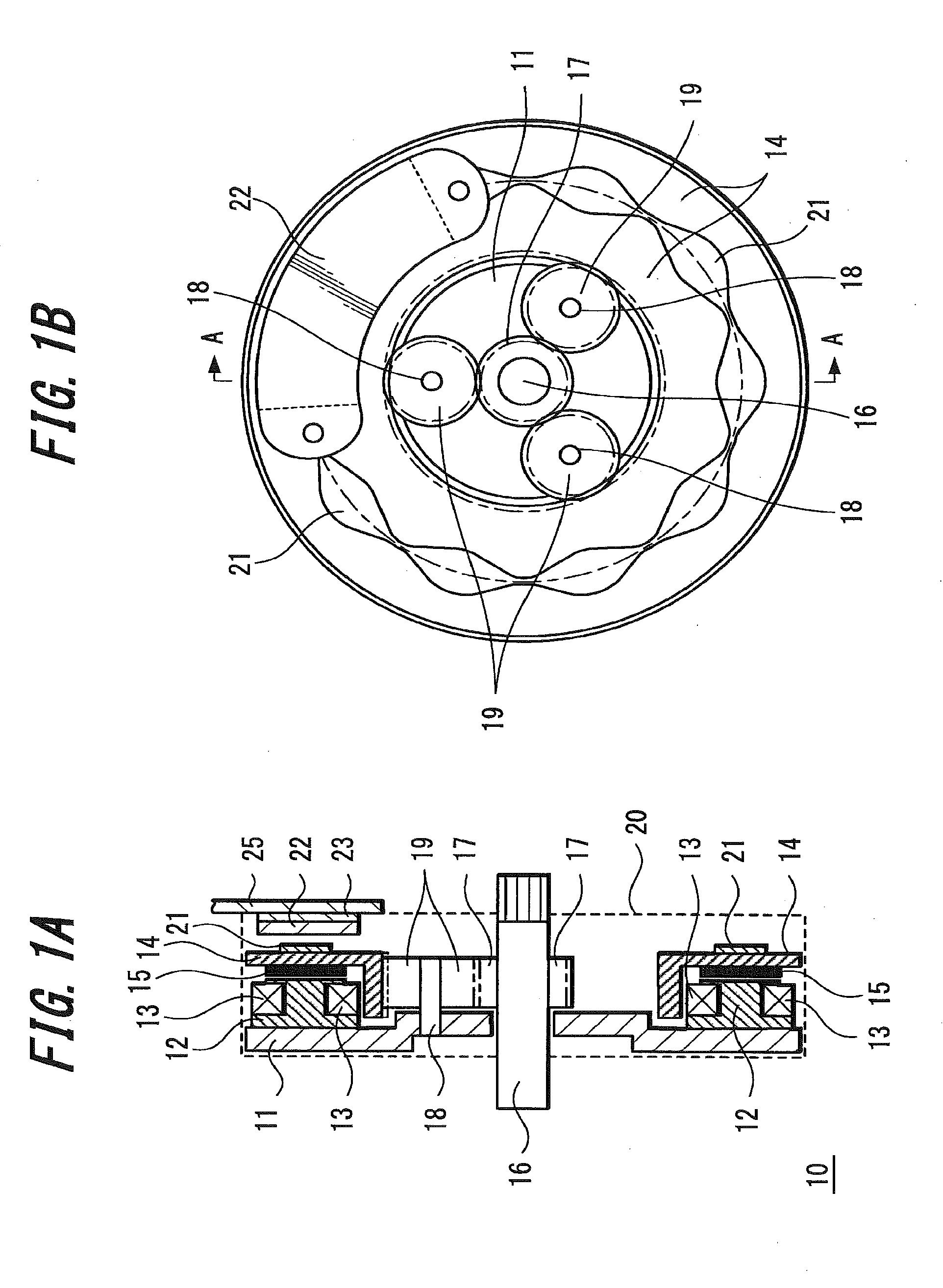
[0037]FIG. 1A and FIG. 1B illustrate schematic configuration diagrams of a brushless motor as an embodiment of the present invention. FIG. 1A illustrates a cross section of the motor, and FIG. 1B illustrates a plan view of the motor viewed from the right side in FIG. 1A. FIG. 1A is a cross section at a line A-A of FIG. 1B.

[0038]A brushless motor 10 illustrated in FIG. 1A and FIG. 1B includes a stator comprising a coil 13, and a rotor 14 to which a magnet 15 has been attached, and between the cylindrical internal surface of the rotor 14 and a rotation axis 16, three reduction gears 19 each comprising a planetary gear are provided.

[0039]The reduction gear 19 is in a shape of a column, and is engaged with a joint 17 of the rotation axis 16 and the internal surface of the rotor 14 with gears, respectively. A central axis 18 of the reduction gear 19 is attached to a base plate 11 to which a support member (core of the coil) 12 of the stator (coil) 13 is attached.

[0040]The magnet 15 is at...


PUM


Abstract

A motor having a sensor to detect a rotation angle that enables reduction in size and weight is provided.
The motor may include a reduction gear having a planetary gear, which is provided between a rotor and a rotation axis of the motor, a conductor pattern periodically changing in width, which is formed on a surface perpendicular to the rotation axis of the rotor, and a rotation angle detection sensor, which is provided to oppose the conductor pattern.

Description

TECHNICAL FIELD[0001]The present invention relates to a motor having a rotation angle detection sensor for detecting the position of a rotor (rotating body) of the motor.BACKGROUND ART[0002]In a brushless DC motor, an angle sensor for a rotor of the motor is provided with the aim of obtaining angle information of the rotor for controlling rectification of a stator of the motor.[0003]As the angle sensor, the method of detecting the magnetic field of a permanent magnet of the rotor is common.[0004]In contrast, when finer control is necessary, a resolver for detecting the angle of a rotation axis is used (for example, see Patent Document 1).[0005]Meanwhile, in a brushless motor, a configuration may be adopted in which a reduction gear is provided between a rotor and a rotation axis of the motor and in which the rotation axis is rotated at the number of revolutions smaller than the original number of revolutions of the motor.[0006]FIG. 7A through FIG. 7C illustrate schematic configurati...

Claims


Application Information

Patent Timeline
IPC IPC(8): H02K11/00
CPCH02K7/116H02K29/12H02K21/24
Inventor YAMAGATA, TETSUONAGASAWA, HIROAKI
Owner SUMIDA CORP
Why Eureka
Try Eureka