
Hybrid distribution transformer with an integrated voltage source converter

a technology of transformers and voltage sources, applied in the field of hybrid distribution transformers, can solve the problems of voltage disturbances costing millions of dollars every year to industries around the world, and the conventional distribution transformer employed in present-day power distribution systems cannot protect digital loads from poor power quality, so as to reduce the variation of output voltag

Active Publication Date: 2010-09-02
HITACHI ENERGY SWITZERLAND AG
View PDF61 Cites 30 Cited by
  • Summary
  • Abstract
  • Description
  • Claims
  • Application Information

AI Technical Summary

Benefits of technology

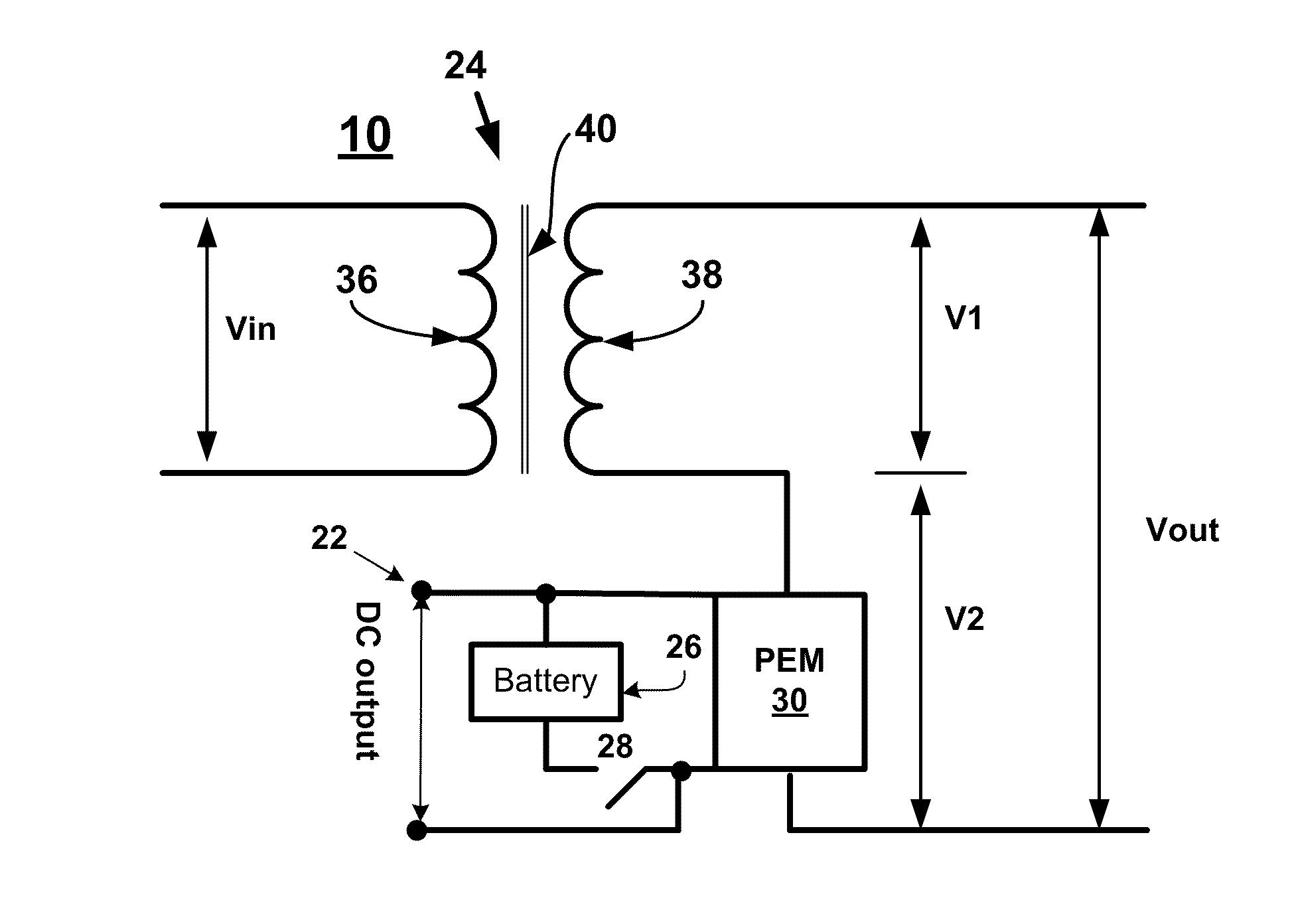
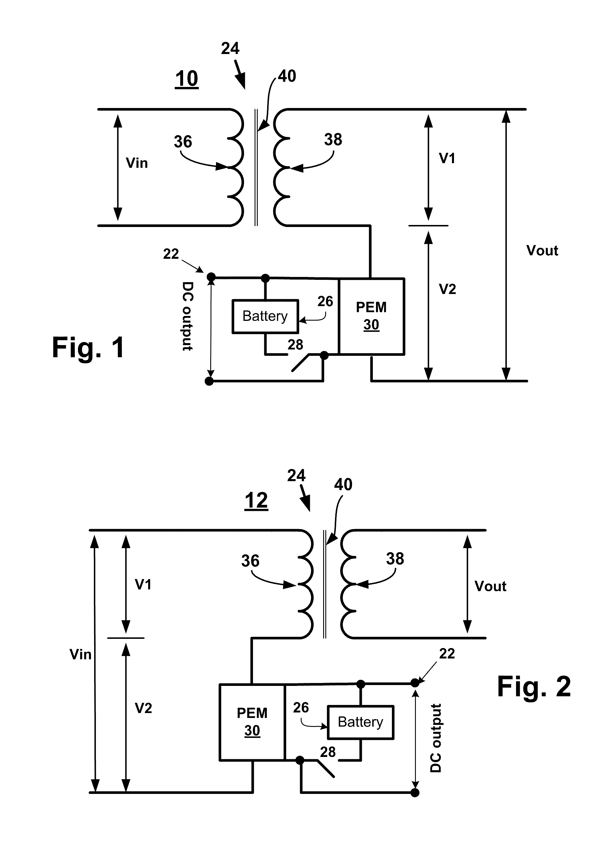
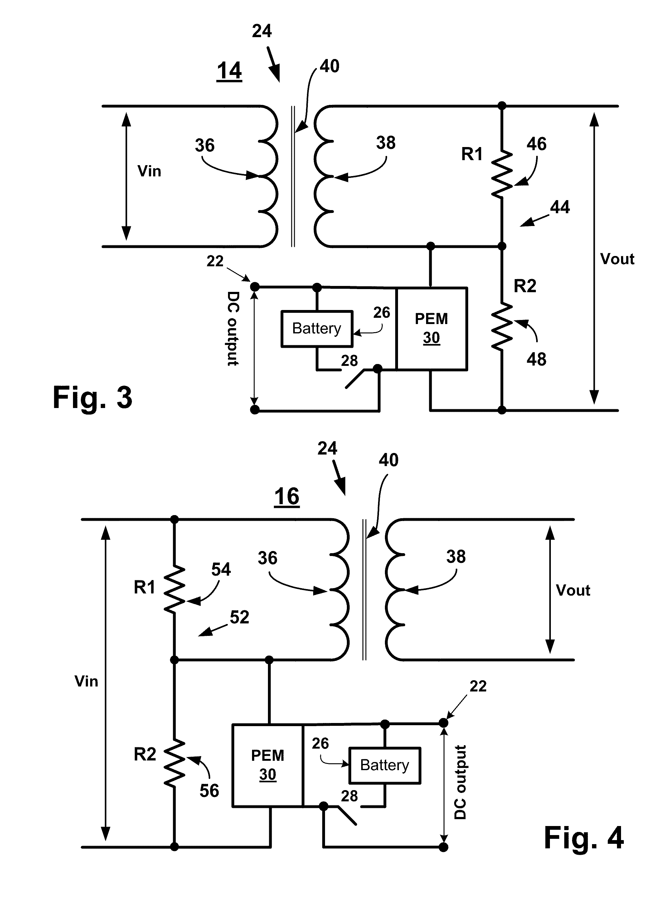
[0006]In accordance with the present invention, a hybrid distribution transformer is provided having a primary side for receiving input voltage and current from a source and a secondary side for providing output voltage and current to a load. The hybrid transformer includes a ferromagnetic core and a winding structure that includes first and second windings wound around the core. One of the first and second windings is a primary winding for connection to the source and one of the first and second windings is a secondary winding for connection to the load. A voltage source converter is connected to the first winding and is operable to convert between DC and AC voltages. The voltage source converter is connected to the first winding and includes at least one switching bridge that has two or more switching devices. A DC bus is connected in parallel with the at least one switching bridge. A controller is operable to control the at least one switching bridge to control the power factor on the primary side of the hybrid transformer and to reduce variations in the output voltage in the event of a change in the input voltage.

Problems solved by technology

A conventional distribution transformer employed in present day power distribution systems cannot protect digital loads against poor power quality, such as sags / swells / distortion.
It is estimated that voltage disturbances cost millions of dollars every year to industries around the world.

Method used


Image

  • Hybrid distribution transformer with an integrated voltage source converter
  • Hybrid distribution transformer with an integrated voltage source converter
  • Hybrid distribution transformer with an integrated voltage source converter

Examples


seventh embodiment

[0060]a hybrid transformer constructed in accordance with the present invention is shown in FIG. 7 and is designated by the reference numeral 66. The hybrid transformer 66 has substantially the same construction as the hybrid transformer 18, except the hybrid transformer 66 has a PEM 31. In addition, the PEM 31 is connected such that the output terminals of the hybrid transformer 66 are connected to the first extremity of the secondary winding 38 (or an outer tap) and an output line 170 from the PEM 31.

eighth embodiment

[0061]a hybrid transformer constructed in accordance with the present invention is shown in FIG. 8 and is designated by the reference numeral 68. The hybrid transformer 68 has substantially the same construction as the hybrid transformer 20, except the hybrid transformer 68 has a PEM 31. In addition, the PEM 31 is connected such that the input terminals of the hybrid transformer 68 are connected to the first extremity of the primary winding 36 (or an outer tap) and the line 170 from the PEM 31.

ninth embodiment

[0062]a hybrid transformer constructed in accordance with the present invention is shown in FIG. 9 and is designated by the reference numeral 76. The hybrid transformer 76 includes an electromagnetic transformer 78, which has a single primary winding 80 and a pair of secondary windings 82, 84 wound around a ferromagnetic core 86. The PEM 30 is connected to ends of the secondary winding 84.


PUM


Abstract

A hybrid distribution transformer is provided that includes an electromagnetic transformer and a voltage source converter that is operable to reduce fluctuation in the output voltage of the hybrid distribution transformer in the event of an increase or decrease in the input voltage.

Description

CROSS-REFERENCE TO RELATED APPLICATION[0001]This application claims the benefit of U.S. provisional patent application No. 61 / 156,300 filed on Feb. 27, 2009, U.S. provisional patent application No. 61 / 163,311 filed on Mar. 25, 2009 and U.S. provisional patent application No. 61 / 223,872 filed on Jul. 8, 2009, all of which are hereby incorporated by reference in their entirety.BACKGROUND OF THE INVENTION[0002]This invention relates to transformers and more particularly to a hybrid distribution transformer utilizing power electronics.[0003]Modern society's movement into the digital age is necessitating the development of a more reliable supply of high-quality electricity. An indispensible component in the supply of electricity to end-users is a distribution transformer. A conventional distribution transformer converts electricity at one voltage to electricity at another voltage, either of higher or lower value. A transformer achieves this voltage conversion using a primary winding and ...

Claims


Application Information

Patent Timeline
IPC IPC(8): H02M7/00
CPCH02M1/4216H02M1/4233Y02B70/126H02M5/4585H02M5/10Y02B70/10H02M1/0093H02M1/4258
Inventor HAJ-MAHARSI, MOHAMED Y.BALA, SANDEEPTANG, LE
Owner HITACHI ENERGY SWITZERLAND AG
Learn More