
Method for improving synchronization precision of data transmission and system thereof

a technology of data transmission and synchronization precision, applied in the field of communication, can solve the problems of difficult improvement of measurement precision, limited precision of fiber delay measurement, and relative low precision, and achieve the effect of improving the precision of data synchronization

Inactive Publication Date: 2010-09-02
SHENZHEN GRENTECH CO LTD
View PDF7 Cites 16 Cited by
  • Summary
  • Abstract
  • Description
  • Claims
  • Application Information

AI Technical Summary

Benefits of technology

[0005]It is an object of the present invention to provide a method for improving synchronization precision of data transmission and a system thereof.
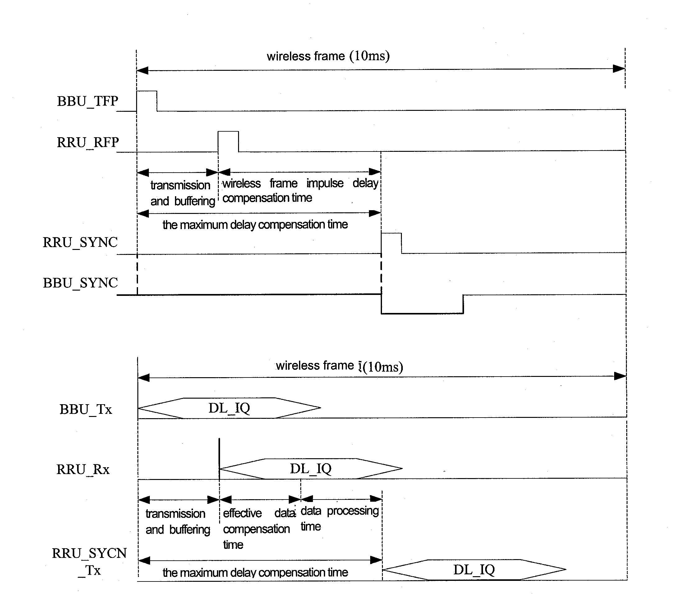
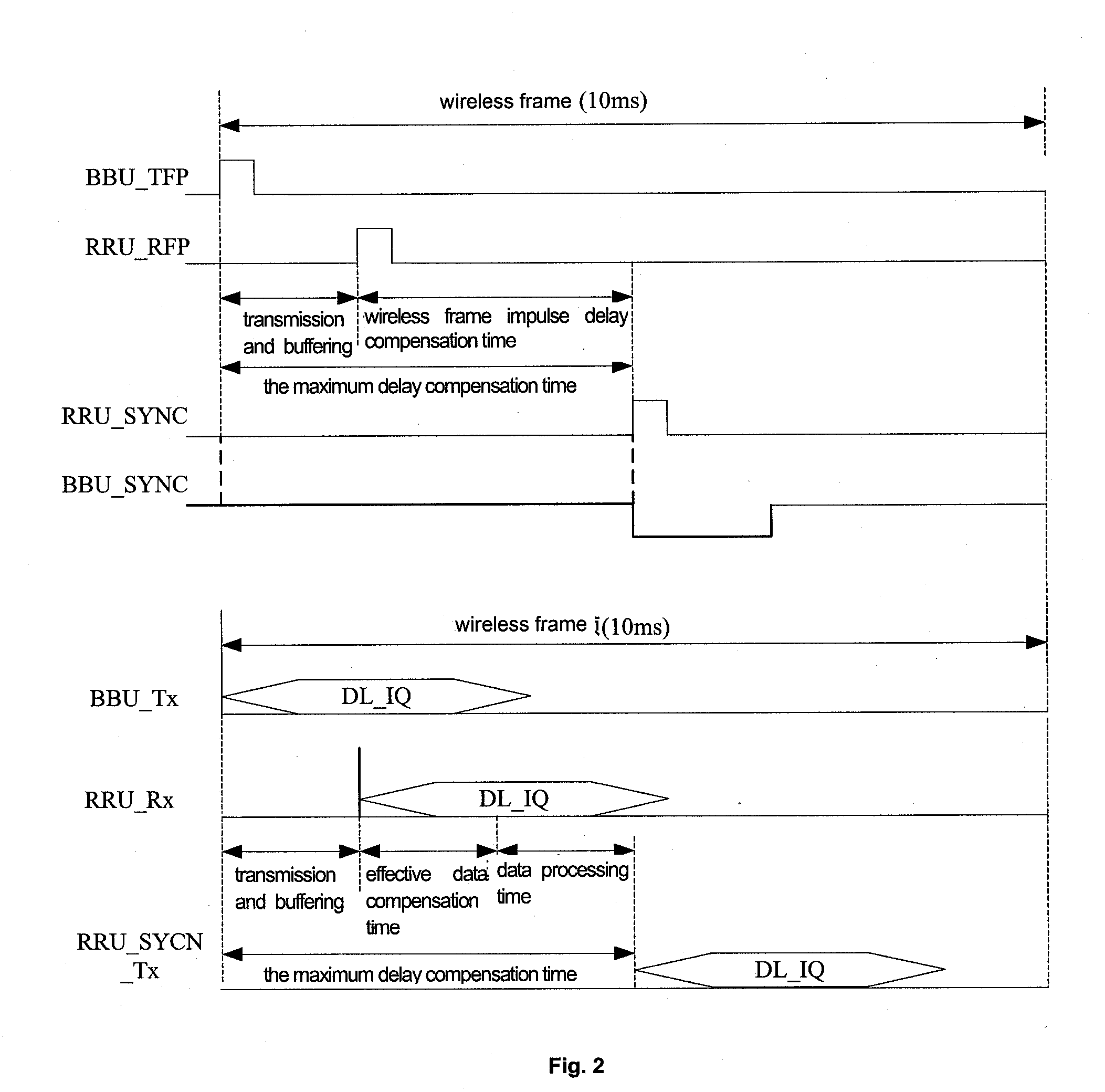
[0031]It can seen from the above technical solution that after receiving the uplink or downlink data frame, frame parsing is performed to the wireless frame impulse signal and the carrier data which are then processed with delay compensation to enable the carrier data can be sent out simultaneously when the wireless frame impulse arrives. With the present invention, the precision of delay compensation reaches several nano-seconds, which greatly improves the precision of data synchronization.

Problems solved by technology

However, the precision of the fiber delay measurement is limited by the current technique condition.
Normally, the precision is relative low, and it is difficult to improve the measurement precision.
In the case of multi-level RRU concatenation, the fiber delay measure error of the optical fiber link is relative large.

Method used


Image

  • Method for improving synchronization precision of data transmission and system thereof
  • Method for improving synchronization precision of data transmission and system thereof
  • Method for improving synchronization precision of data transmission and system thereof

Examples


Embodiment Construction

[0035]Many aspects of the present invention will be described in detail with reference to the accompanying drawings.

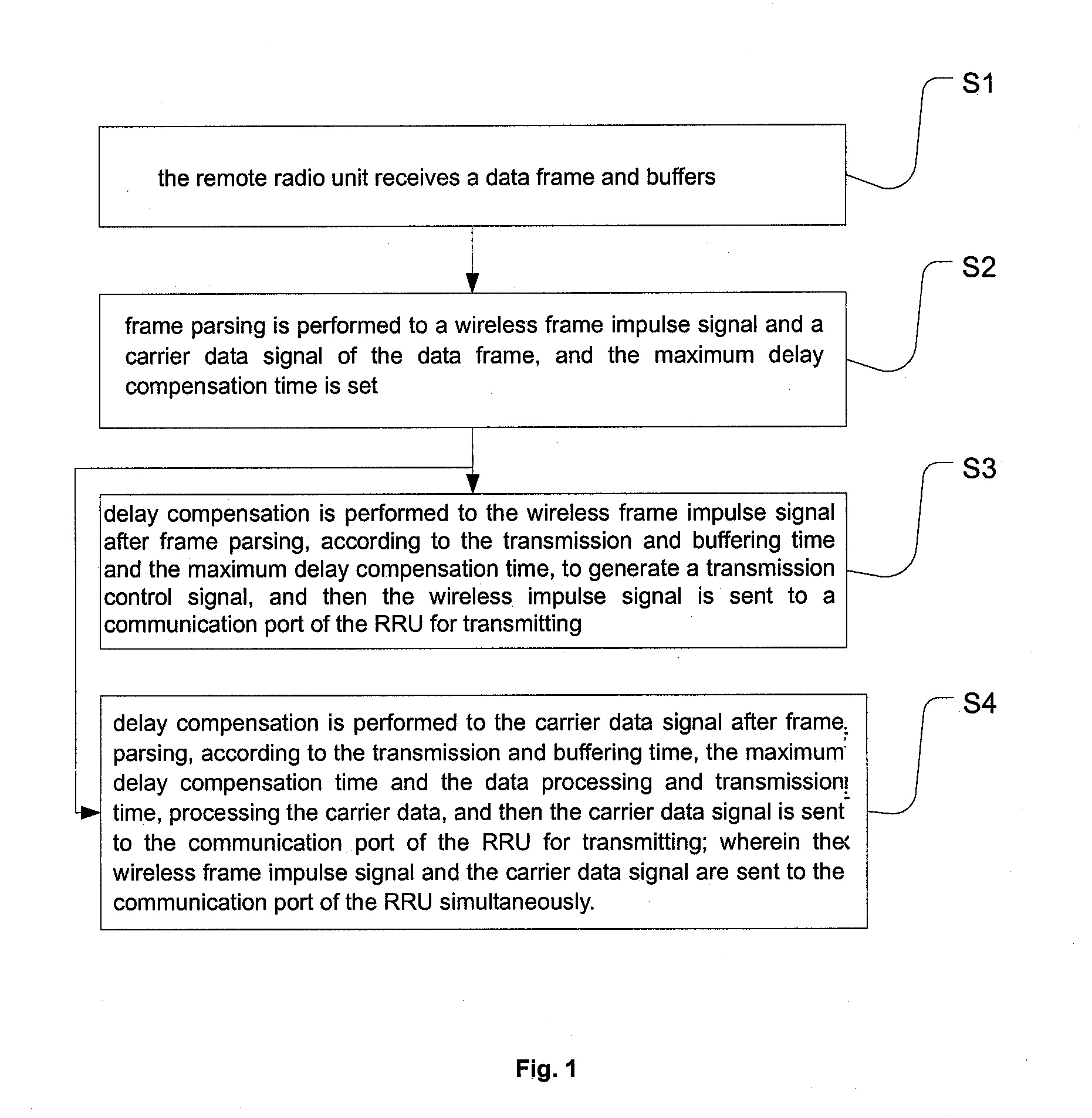
[0036]In order to realize the delay compensation to the communication data, and to improve the synchronization precision of the air interface, the present invention provides a method for improving the synchronization precision of data transmission, as shown in FIG. 1, the method comprises:

[0037]Step S1, a data frame is received and buffered by the RRU (Radio Remote Unit).

[0038]Step S2, frame parsing is performed to a wireless frame impulse signal and a carrier data signal of the data frame, and the maximum delay compensation time is set. The wireless frame impulse signal and the carrier data after the frame parsing are respectively processed in Step S3 and Step S4.

[0039]Step S3, delay compensation is given to the wireless frame impulse signal after the frame parsing, according to the transmission and buffering time and the maximum delay compensation time, and then the ...


PUM


Abstract

A method for improving synchro precision of data transmission and system thereof are disclosed. The method includes the following steps: RRU receives a data frame and buffers; frame-parses to a wireless frame impulse signal and a carrier wave data signal of the data frame, setting the maximum time-lapse compensating time; a time-lapse is redeemed to the wireless frame impulse signal after parsing, according to the time of transmission and buffering, and the maximum time-lapse compensating time, and then sends to the communication port of RRU to transmit; a time-lapse is redeemed to the carrier wave data signal after parsing, according to the time of transmission and buffering, the maximum time-lapse compensating time, and transmission time of processing data, the carrier wave data is processed, and then is sent to the communication port of RRU to transmit; the wireless frame impulse signal and the carrier wave data signal are sent to the communication port of RRU simultaneously. The solution redeems the carry time-lapse for transmission data, so that the redeeming precision can reach multiple seconds, thus improving synchro precision of the data in an effective manner.

Description

TECHNICAL FIELD[0001]The present invention relates to the field of communications, and in particular to a method for improving synchronization precision of data transmission and a system thereof.BACKGROUND OF THE INVENTION[0002]In the TD-SCDMA system, the required synchronization precision of air interface is ⅛ chip width, i.e. about 100 ns. In the base station model of the baseband unit (BBU) plus the remote radio unit (RRU), synchronization precision of the air interface is determined by the precision of fiber delay measurement and the precision of synchronization delay compensation of the air interface.[0003]However, the precision of the fiber delay measurement is limited by the current technique condition. Normally, the precision is relative low, and it is difficult to improve the measurement precision. In the case of multi-level RRU concatenation, the fiber delay measure error of the optical fiber link is relative large.[0004]A high-precision delay compensation method is thus s...

Claims


Application Information

Patent Timeline
IPC IPC(8): H04J3/06H04B7/26H04W28/14H04W56/00
CPCH04W56/00
Inventor ZHANG, MINGSHENGXIANG, SHENGWEN
Owner SHENZHEN GRENTECH CO LTD
Learn More