
Frequency converting system

a technology of frequency conversion and conversion system, which is applied in the direction of amplitude demodulation, transmission monitoring, instruments, etc., can solve the problems of lowering the s/n ratio of the signal, inter-modulation distortion, and measurement error, so as to achieve high dynamic range and facilitate digital processing

Inactive Publication Date: 2010-09-02
ANRITSU CORP
View PDF12 Cites 19 Cited by
  • Summary
  • Abstract
  • Description
  • Claims
  • Application Information

AI Technical Summary

Benefits of technology

[0010]An object of the present invention is to provide a frequency converting system which converts, in order to analyze a spectrum of a broadband signal of a high-frequency band in real time, the broadband signal of the high-frequency band into a signal of a lower-frequency band in which digital processing is made easier, in a high dynamic range.

Problems solved by technology

Accordingly, such an analog signal x(t) causes inter-modulation distortion to occur in the output signal of the mixer beyond the appropriate operation range of the mixer 12, and causes an error to occur in the measurement result.
However, in this circuit configuration, there is the problem that the level of the average power input to the mixer 12 is lowered by the attenuator, consequently, the S / N ratio of the signal is lowered, and the measurement dynamic range becomes narrow.
However, each of these systems is a system in which the spectrum of the input signal is analyzed by the sweep of the local signal L, and hence there is the problem that the analog signal x(t) cannot be theoretically measured in real time.

Method used


Image

  • Frequency converting system
  • Frequency converting system
  • Frequency converting system

Examples


Embodiment Construction

[0064]A frequency converting system according to an embodiment of the present invention will be described below in detail with reference to the accompanying drawings.

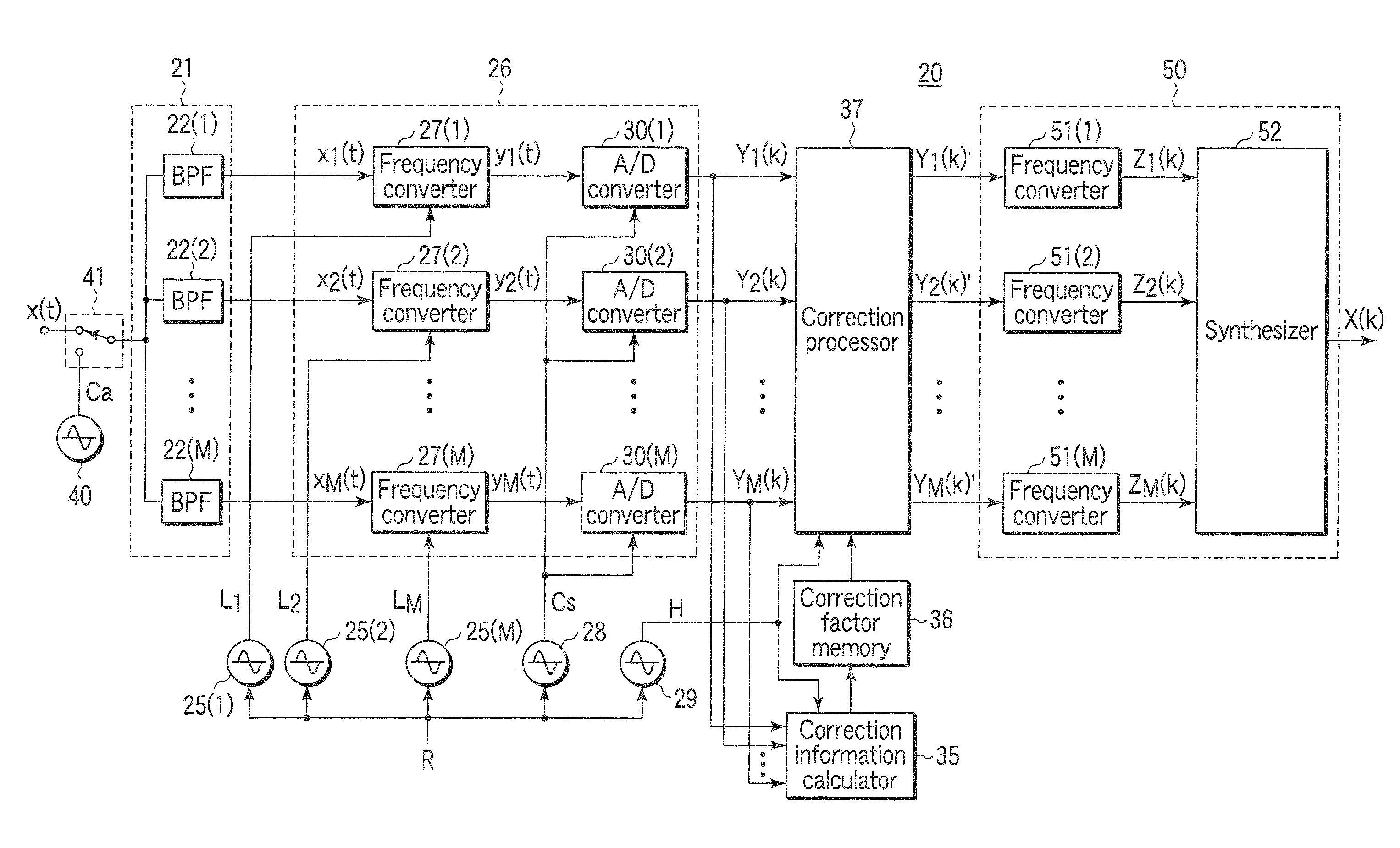
[0065]FIG. 1 is a block diagram showing the circuit configuration of a frequency converting system 20 according to the embodiment of the present invention. In the frequency converting system 20 shown in FIG. 1, a broadband analog signal in the high-frequency band of several GHz such as the high-frequency band of the OFDM system used in the mobile communication, and extending over a wide band of several tens of MHz is input to a signal branching section 21 as an input signal x(t). In the frequency converting system 20, the input signal x(t) is converted, for the digital signal processing, into a signal of a low frequency band of, for example, several hundred MHz.

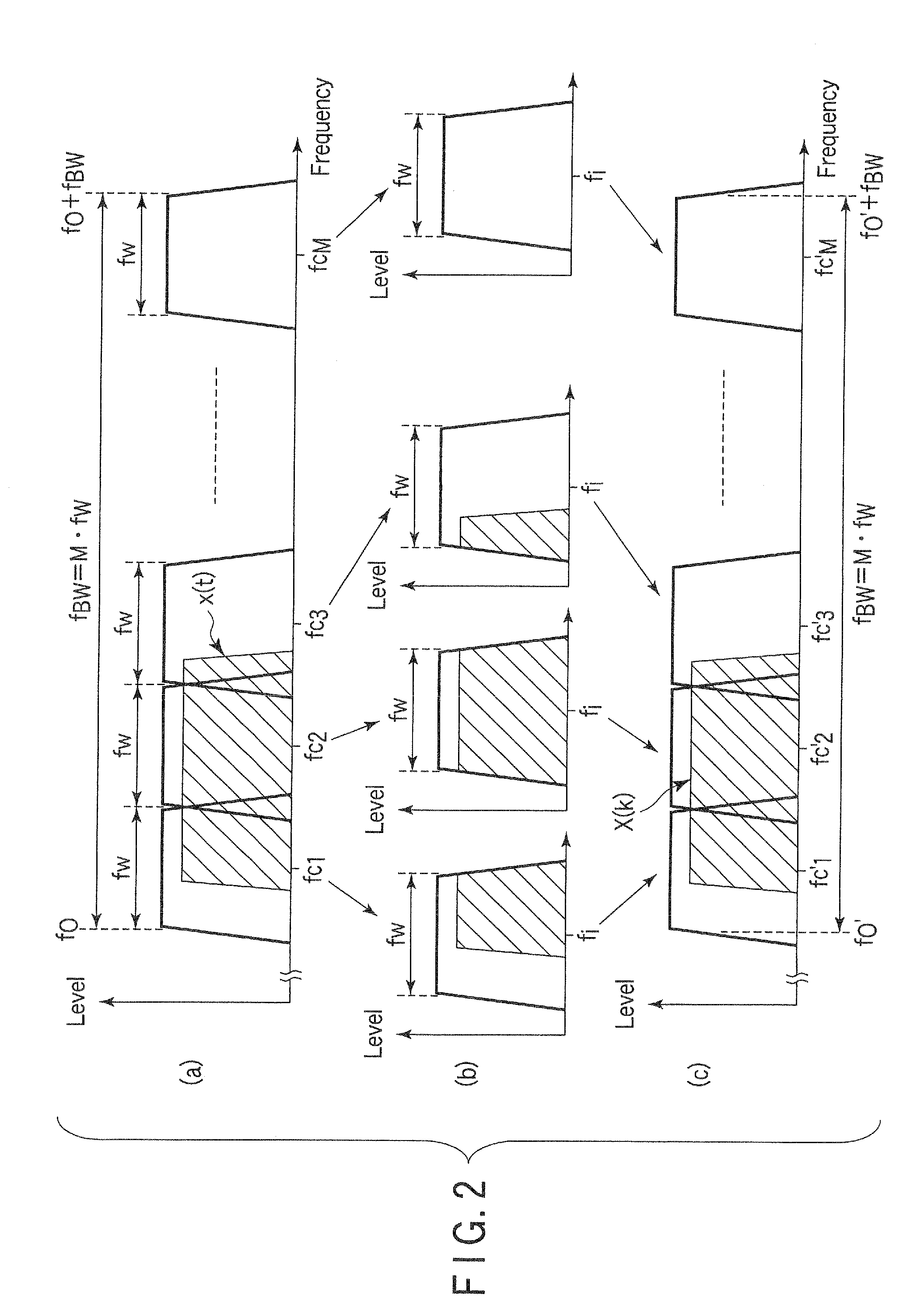
[0066]In the signal branching section 21, the predetermined frequency domain f0 to (f0+fBW) in which the analog input signal x(t) is included is divided into M c...


PUM


Abstract

In a frequency converting system, an input signal x(t) is supplied to a signal branching section for dividing a predetermined frequency domain into M bands, extracting signal components of the respective divided bands. The respective signal components and local signals each including a frequency difference corresponding to a predetermined intermediate frequency with respect to a center frequency of each band are input to a frequency converting part. The signals of the respective divided bands are converted into signals of intermediate frequency bands each including the predetermined intermediate frequency as the center frequency, the conversion outputs are sampled by using a common clock signal, whereby the conversion outputs are converted into digital signals. Further, after being subjected to phase correction processing, the digital signals are subjected to frequency conversion and combination processing by a signal regeneration part.

Description

CROSS-REFERENCE TO RELATED APPLICATIONS[0001]This application is based upon and claims the benefit of priority from prior Japanese Patent Application No. 2009-045595, filed Feb. 27, 2009, the entire contents of which are incorporated herein by reference.BACKGROUND OF THE INVENTION[0002]1. Field of the Invention[0003]The present invention relates to a frequency converting system for waveform-analyzing a high-frequency and broadband analog signal utilized in communication such as mobile communication, and the like or converting a frequency for a digital analysis device for spectrum-analyzing the analog signal and, more particularly, to a frequency converting system capable of reducing distortion caused in a converted wave resulting from instantaneous power contained in a broadband analog signal, and realizing a broadband converted wave of a high dynamic range.[0004]2. Description of the Related Art[0005]A wireless signal utilized in communication such as mobile communication is a modu...

Claims


Application Information

Patent Timeline
IPC IPC(8): H04B3/46H03M1/12
CPCH03D7/00G01R23/16
Inventor FUSE, MASAAKISEKIYA, HITOSHI
Owner ANRITSU CORP
Learn More