Turbine airfoil cooling system with near wall pin fin cooling chambers

a cooling system and turbine airfoil technology, which is applied in the direction of engine fuction, blade accessories, machines/engines, etc., can solve the problems of reducing the useful life of the turbine blade, the likelihood of failure, and localized hot spots, and achieve the effect of increasing the cooling effect of the cooling system

Inactive Publication Date: 2010-09-02
SIEMENS ENERGY INC
View PDF7 Cites 57 Cited by
  • Summary
  • Abstract
  • Description
  • Claims
  • Application Information

AI Technical Summary

Benefits of technology

[0004]This invention relates to a cooling system for turbine airfoils used in turbine engines. In particular, the turbine airfoil cooling system may include an internal cavity positioned between outer walls of the turbine airfoil. The cooling system may include a suction side near wall cooling chamber immediately adjacent to the outer wall forming a suction side of the turbine airfoil. The cooling system may also include a pressure side near wall cooling chamber immediately adjacent to the outer wall forming a pressure side of the turbine airfoil. The suction and pressure side near wall cooling chambers may include a plurality of pin fins to increase the cooling effectiveness of the cooling system and to accommodate localized hot spots in the turbine blade.

Problems solved by technology

In addition, turbine blades often contain cooling systems for prolonging the life of the blades and reducing the likelihood of failure as a result of excessive temperatures.
However, centrifugal forces and air flow at boundary layers often prevent some areas of the turbine blade from being adequately cooled, which results in the formation of localized hot spots.
Localized hot spots, depending on their location, can reduce the useful life of a turbine blade and can damage a turbine blade to an extent necessitating replacement of the blade.

Method used


Image

  • Turbine airfoil cooling system with near wall pin fin cooling chambers
  • Turbine airfoil cooling system with near wall pin fin cooling chambers
  • Turbine airfoil cooling system with near wall pin fin cooling chambers

Examples


Embodiment Construction

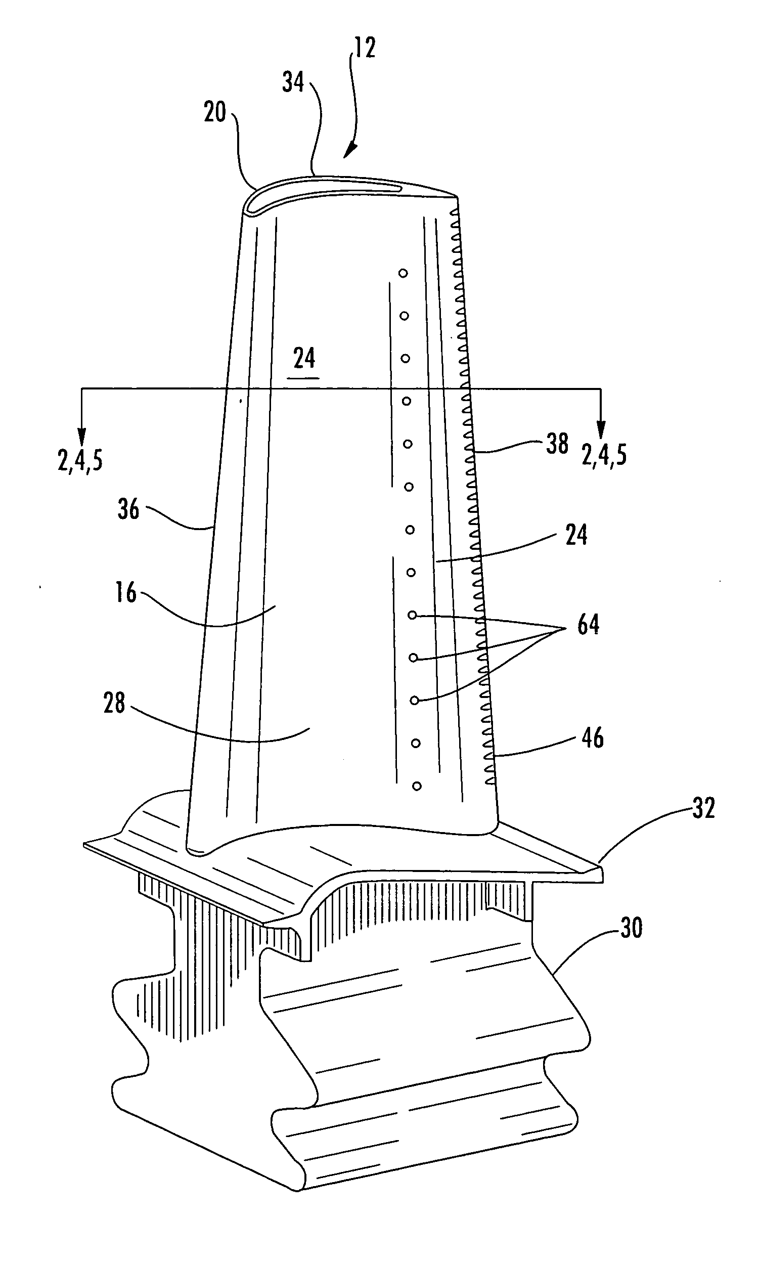
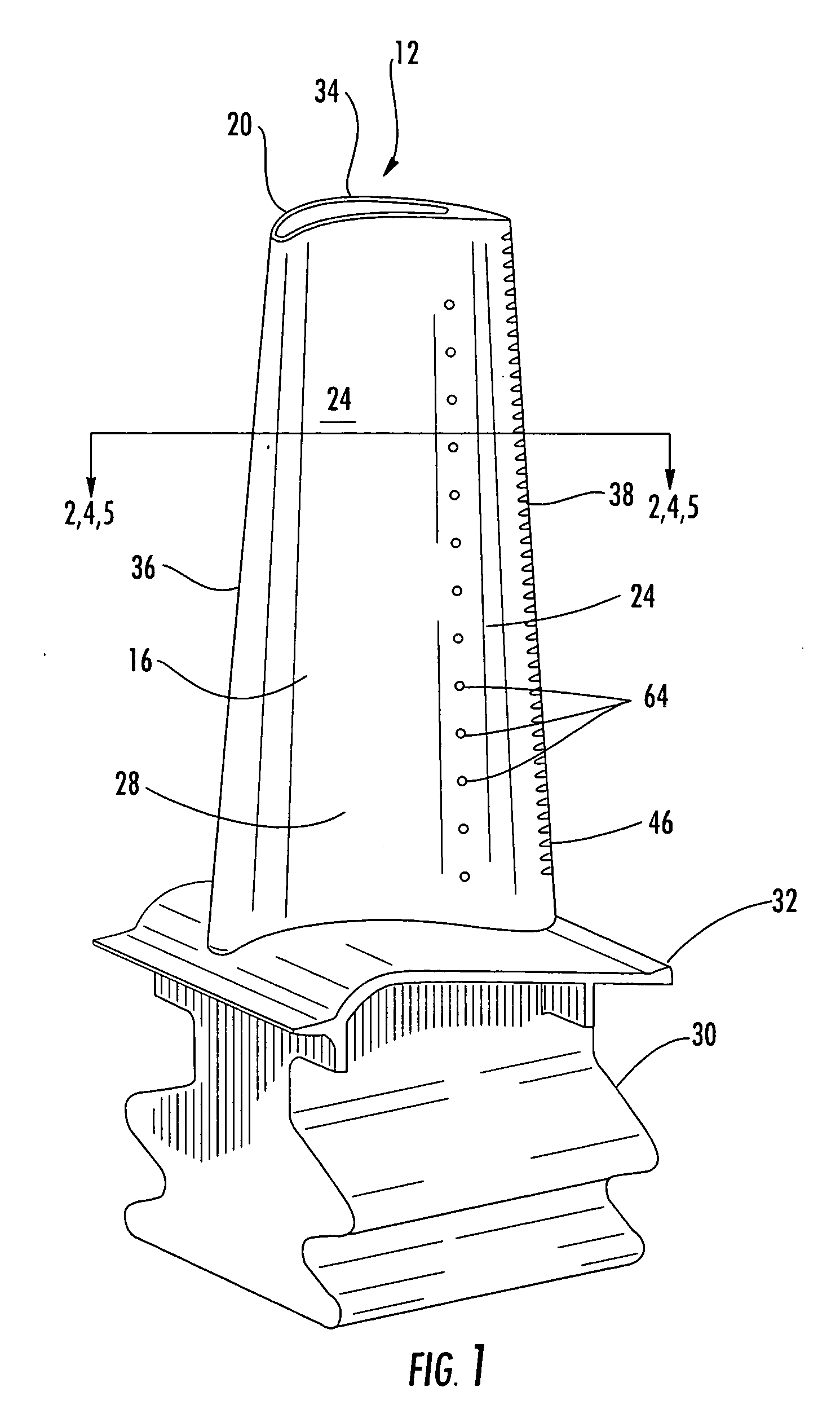
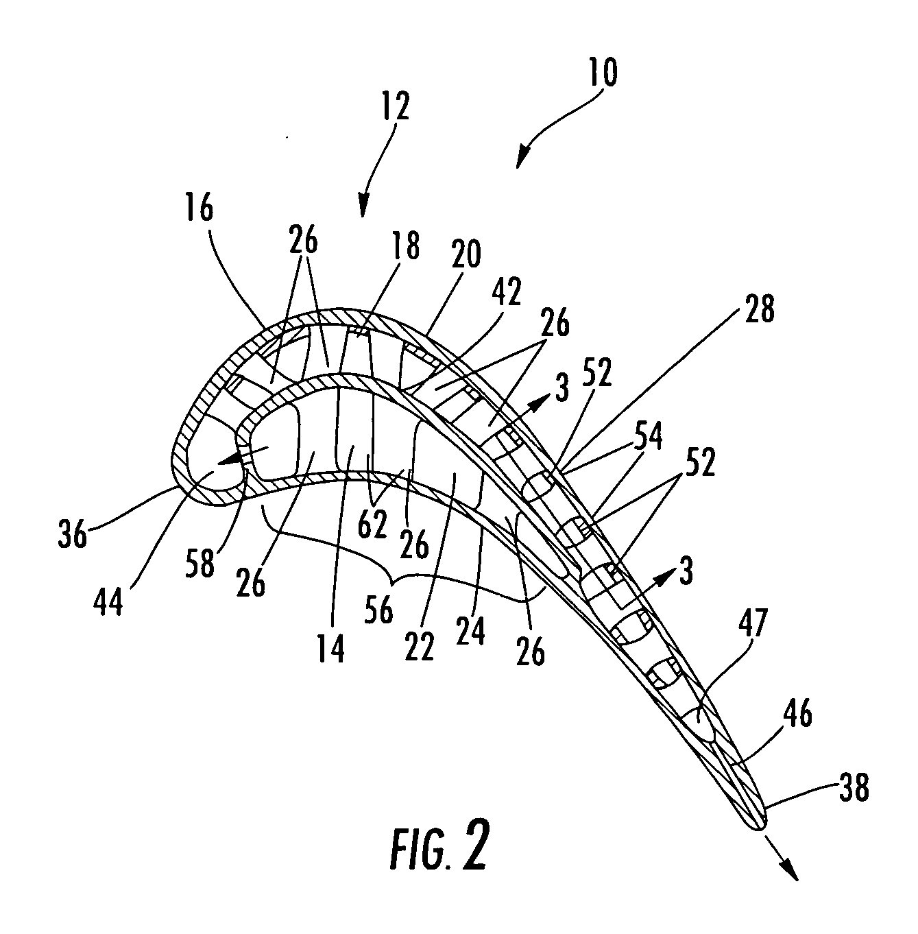
[0021]As shown in FIGS. 1-5, this invention is directed to a turbine airfoil cooling system 10 for a turbine airfoil 12 used in turbine engines. In particular, the turbine airfoil cooling system 10 includes a plurality of internal cavities 14, as shown in FIG. 2, positioned between outer walls 16 of the turbine airfoil 12. The cooling system 10 may include a suction side near wall cooling chamber 18 immediately adjacent to the outer wall 16 forming a suction side 20 of the turbine airfoil 12. The cooling system 10 may also include a pressure side near wall cooling chamber 22 immediately adjacent to the outer wall 16 forming a pressure side 24 of the turbine airfoil 12. The suction and pressure side near wall cooling chambers 18, 22 may include a plurality of pin fins 26 to increase the cooling effectiveness of the cooling system 10 and to accommodate localized hot spots in the turbine blade 12.

[0022]The turbine airfoil 12 may be formed from a generally elongated, hollow airfoil 28 c...


PUM


Abstract

A cooling system for a turbine airfoil of a turbine engine having a suction side near wall cooling chamber extending from the leading edge to the trailing edge. The suction side near wall cooling chamber may include a plurality of pin fins for increasing the cooling effectiveness of the suction side near wall cooling chamber. The pin fins may be formed in two or more regions having varying sizes and quantities per unit area to accommodate different cooling requirements across the airfoil. In one embodiment, cooling fluids may flow in a counterflow manner through the suction side near wall cooling chamber relative to a pressure side near wall cooling chamber. In another embodiment, the cooling fluids may flow from the leading edge through the suction side near wall cooling chamber and be exhausted through slots in the trailing edge.

Description

FIELD OF THE INVENTION[0001]This invention is directed generally to turbine airfoils, and more particularly to cooling systems in hollow turbine airfoils.BACKGROUND[0002]Typically, gas turbine engines include a compressor for compressing air, a combustor for mixing the compressed air with fuel and igniting the mixture, and a turbine blade assembly for producing power. Combustors often operate at high temperatures that may exceed 2,500 degrees Fahrenheit. Typical turbine combustor configurations expose turbine blade assemblies to these high temperatures. As a result, turbine blades must be made of materials capable of withstanding such high 1-5 temperatures. In addition, turbine blades often contain cooling systems for prolonging the life of the blades and reducing the likelihood of failure as a result of excessive temperatures.[0003]Typically, turbine blades are formed from a root portion having a platform at one end and an elongated portion forming a blade that extends outwardly fr...

Claims


Application Information

Patent Timeline
Patent Type & Authority Applications(United States)
IPC IPC(8): F01D5/18
CPCF05D2260/22141F01D5/187
Inventor LIANG, GEORGE
Owner SIEMENS ENERGY INC
Why Eureka
Try Eureka