Cable guide system for a mold forming and extruding machine and a method of use

a mold forming and extruder technology, applied in the field of cable guide system, can solve the problems of mold cracking or breaking, heaving or moving of the ground, cracking and breaking, etc., and achieve the effect of convenient and efficient operation and easy attachmen

Inactive Publication Date: 2010-09-09
CURB SOLUTIONS
View PDF25 Cites 27 Cited by
  • Summary
  • Abstract
  • Description
  • Claims
  • Application Information

AI Technical Summary

Benefits of technology

[0012]A further object of this invention is to provide a cable guide system which is easy to attach to a mold forming and extruding machine.
[0013]Still another object of this invention is to provide a cable guide system which is easy and efficient to operate.
[0014]Still further, an object of this invention is to provide a cable guide system which can position one, two or more flexible reinforcement cables or wires within a compacted and moldable substance which is being extruded from a mold forming machine.

Problems solved by technology

Such cracking and breaking can occur for a number of reasons.
In addition, in southern climates, a mold can crack or break due to the consistency of the soil, the amount of clay and / or sand in the soil.
In northern climates, a large fluctuation in temperatures can cause the ground to heave or move due to freezing and thawing.
For example, a severe winter in parts of Minnesota, Wisconsin, Michigan or upstate New York, where frost is common, can cause the upper layer of the soil to move or heave.
This movement can easily cause a continuous concrete mold having a height of less than about eight inches to heave, crack and / or break.
Another cause of such cracking and breaking can occur if an automobile or truck drives over the curb or edging.
Furthermore, certain soils are more prone to settling due to soil erosion, water runoff, wind, etc. and this too can cause the continuous mold to crack or break at various locations.
When the continuous mold does crack or break, the top and / or side surfaces of adjoining sections can acquire a step or shoulder appearance which is unsightly.
Such an uneven and unsightly appearance destroys the aesthetic appearance of the continuous mold.
This works well for large concrete sections like driveways and walkways but does not lend itself to an elongated narrow strip of curbing or edging.
Some contractors have also tried to insert rigid reinforcement rods into curbs and edgings but this had its drawbacks especially when the curb or edging was molded into a curve or circular shape.
First, it was inefficient in that the cable had to be first cut and positioned in place.
Second, the cable was pushed downward against the ground by the weight of the moldable material.
With the reinforcing cable located adjacent to the ground, the cable may not be able to reduce separation of the mold at points where cracking does occur.
Third, if the cable was initially cut too short, there was no easy way to add additional cable.

Method used


Image

  • Cable guide system for a mold forming and extruding machine and a method of use
  • Cable guide system for a mold forming and extruding machine and a method of use
  • Cable guide system for a mold forming and extruding machine and a method of use

Examples


Embodiment Construction

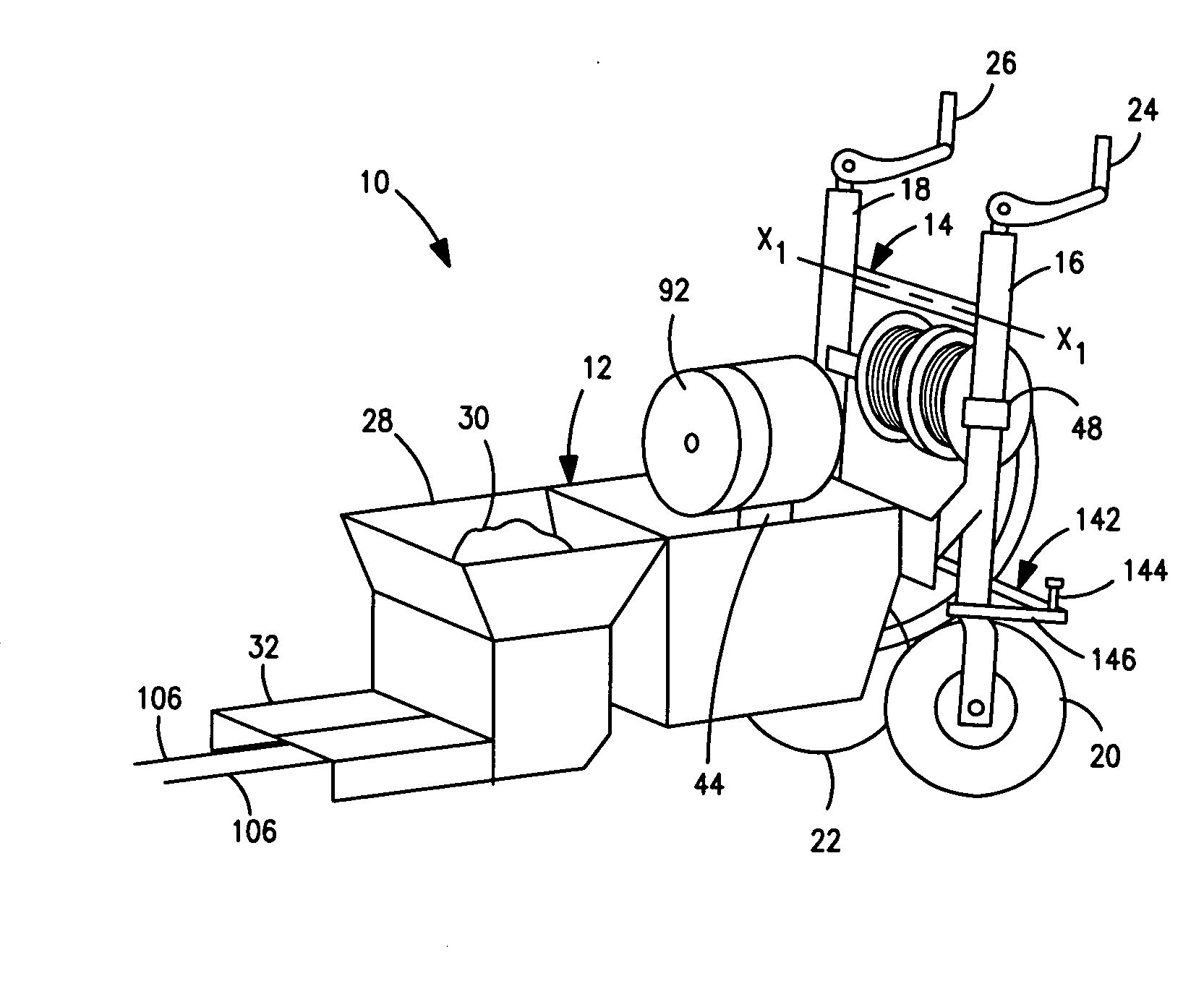
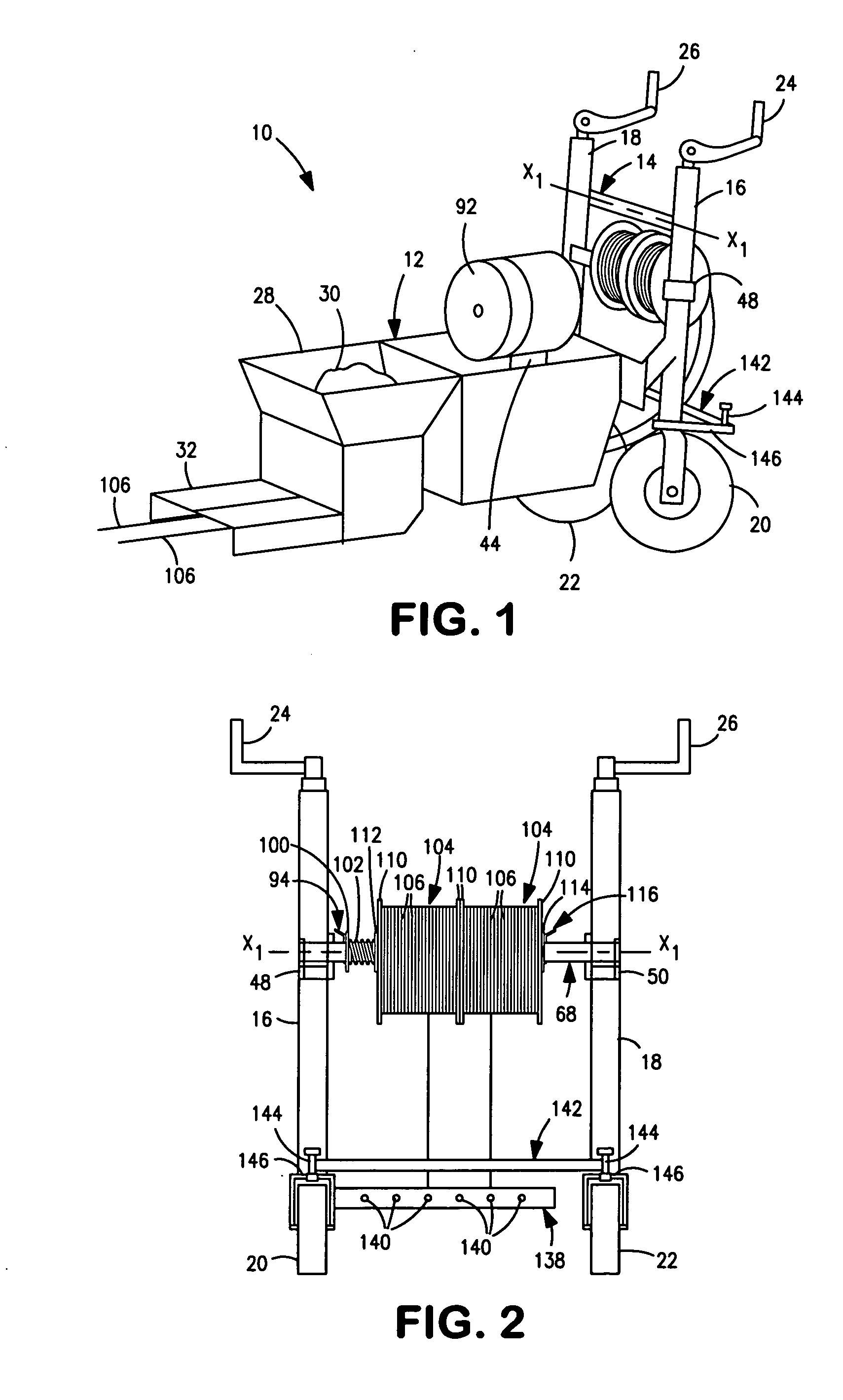
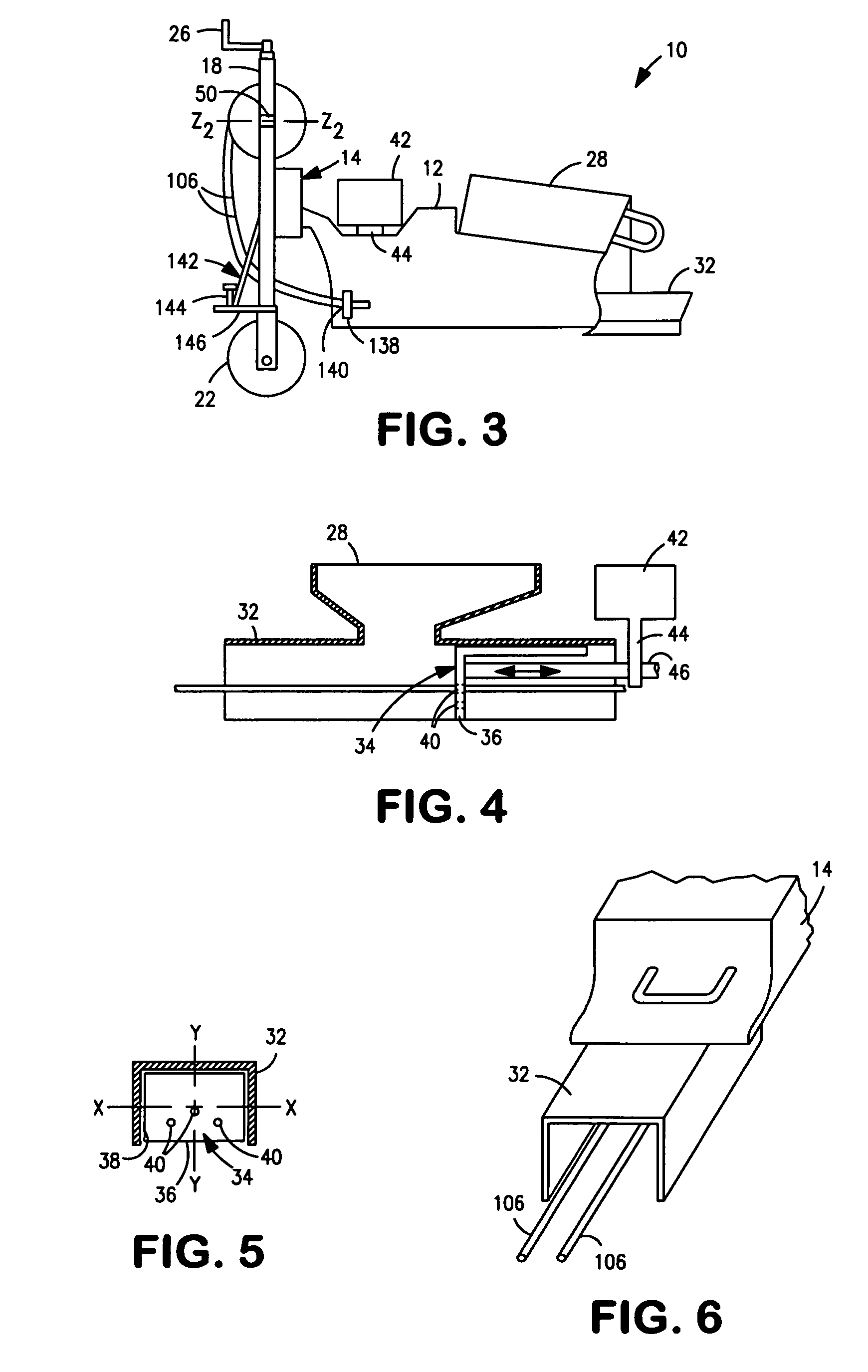
[0035]Referring to FIGS. 1-3, a cable guide system 10 for a mold forming and extruding machine 12 is shown. The machine 12 can be various models of a mold forming and extruding machine 12 which can accommodate different mold units so as to mold curbs, edgings, speed bumps, walkways, sidewalks, etc. The machine 12 includes a frame 14 having a pair of spaced apart vertical members 16 and 18. A pair of rotatable wheels 20 and 22 is secured to a lower portion of the frame 14. Desirably, each of the pair of wheels 20 and 22 is located at the lower end of one of the vertical members 16 and 18. A pair of rotatable handles, 24 and 26, is located at the upper end of each of the vertical members 16 and 18. Each of the handles 24 and 26 is connected to a mechanical mechanism, such as a worm and gear mechanism, not shown, which will enable the frame 14 to be raised or lower with respect to the ground. For example, when the handles 24 and 26 are rotated in a first direction, say clockwise, the f...


PUM

PropertyMeasurementUnit
diameteraaaaaaaaaa
heightaaaaaaaaaa
diameteraaaaaaaaaa

Abstract

A cable guide system and method are disclosed for a mold forming and extruding machine. The machine has a pair of spaced apart vertical members. The cable guide system includes a support shaft secured to the pair of vertical members. The support shaft retains a first stop member, a tensioning device, a spool loaded with a flexible reinforcement cable, and a second stop member. The spool cooperates with the tensioning device to prevent the cable from prematurely unraveling. The cable guide system further includes a guide member located below and forward of the spool and in horizontal alignment with a plunger. The guide member is capable of changing the direction of the flexible reinforcement cable as it is unwound from the spool. The plunger is capable of extruding a moldable substance from the machine while allowing the flexible reinforcement cable to pass through an aperture formed therein.

Description

FIELD OF THE INVENTION[0001]This invention relates to a cable guide system for a mold forming and extruding machine which can extrude a moldable substance along with a flexible reinforcement cable and a method of unwinding and positioning the cable within the mold substance.BACKGROUND OF THE INVENTION[0002]In the past decade, it has become common for many residential and commercial property owners to have a continuous custom concrete curb or edging installed around flower beds, trees gardens, etc. to enhance the appearance of their landscaping. The continuous concrete curb or edging is formed using a portable curb forming and extruding machine such as those manufactured by “Borderline Stamp. Inc.” of Surprise, Ariz., and “The Concrete Edge Company” of Orlando, Fla., as well as others. Such machines typically include a reciprocating ram or an auger to force concrete or other building materials through a mold. Each machine includes a hopper for receiving the material and a motor and g...

Claims


Application Information

Patent Timeline
Patent Type & Authority Applications(United States)
IPC IPC(8): E04B1/06E04G11/22
CPCE04G21/04E04G11/34
Inventor TECHLIN, AARON A.CONRADT, GRAHAM M.TECHLIN, TYLER N.
Owner CURB SOLUTIONS
Why Eureka
Try Eureka