Supercharge Your Innovation With Domain-Expert AI Agents!

Optical processing method and mask

a processing method and optical technology, applied in the field of optical processing methods and masks, can solve the problems of abnormal shape development at the seam, limit of irradiation area,

Inactive Publication Date: 2010-09-09
SONY CORP
View PDF7 Cites 2 Cited by
  • Summary
  • Abstract
  • Description
  • Claims
  • Application Information

AI Technical Summary

Benefits of technology

The present invention provides an optical processing method that can suppress the development of abnormal shapes at the seam portion of light irradiation regions caused by the use of a mask with multiple openings. The method involves moving the irradiation region of light in a direction orthogonal to the mask and superimposing parts of the light irradiation in a seam region with parts of the irradiation in a previous stage. By doing so, the irradiation amount in the seam region becomes equal to the irradiation amount in other regions, resulting in a seamless smooth processing shape. The invention also provides a mask with multiple openings that can be used to form complex 3D shapes by varying the number of openings in different lines.

Problems solved by technology

However, there is a limit with an irradiation area by an excimer laser.
When laser beam irradiation regions via a mask are joined in this manner, an abnormal shape develops at the seam.

Method used


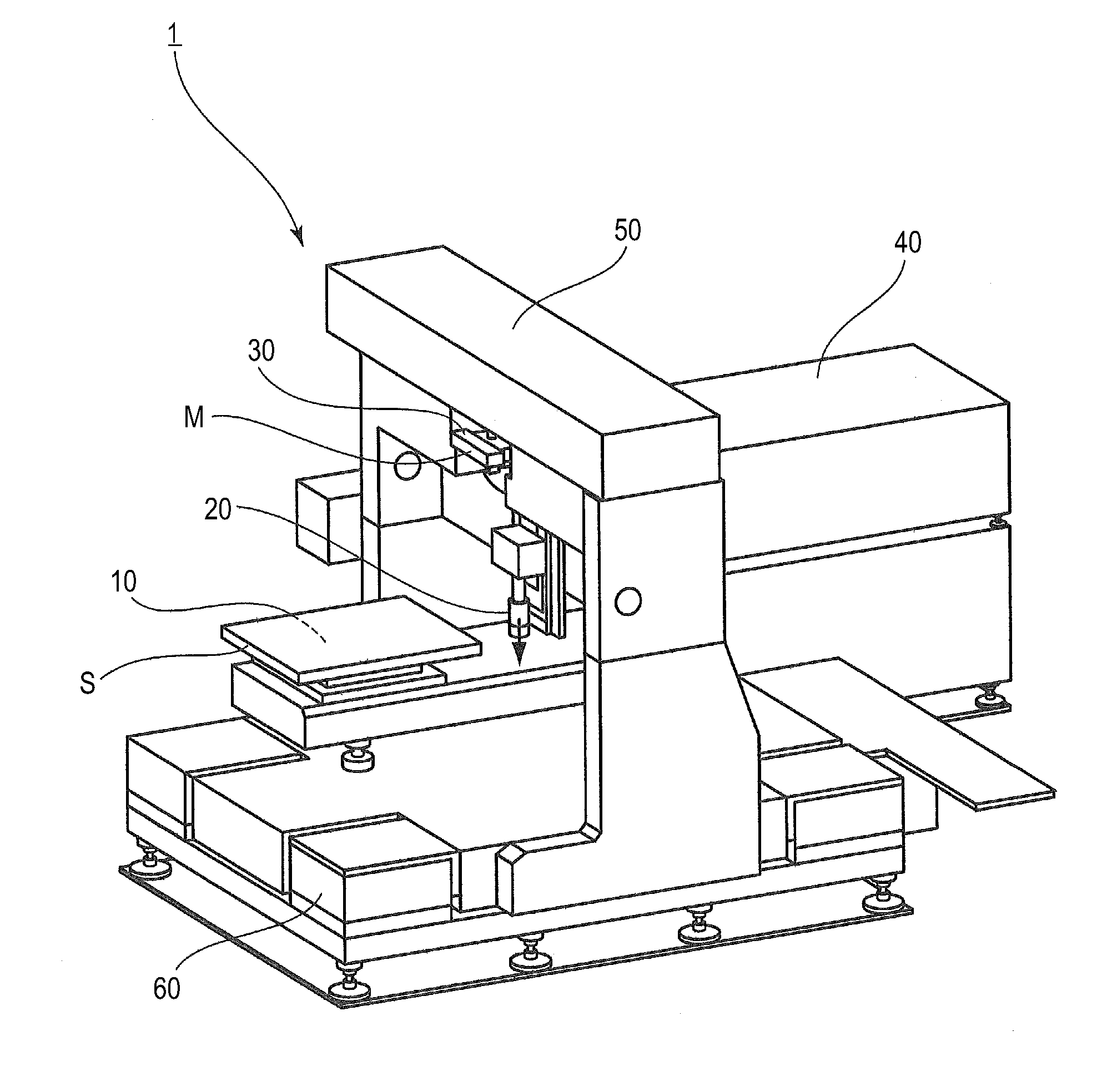
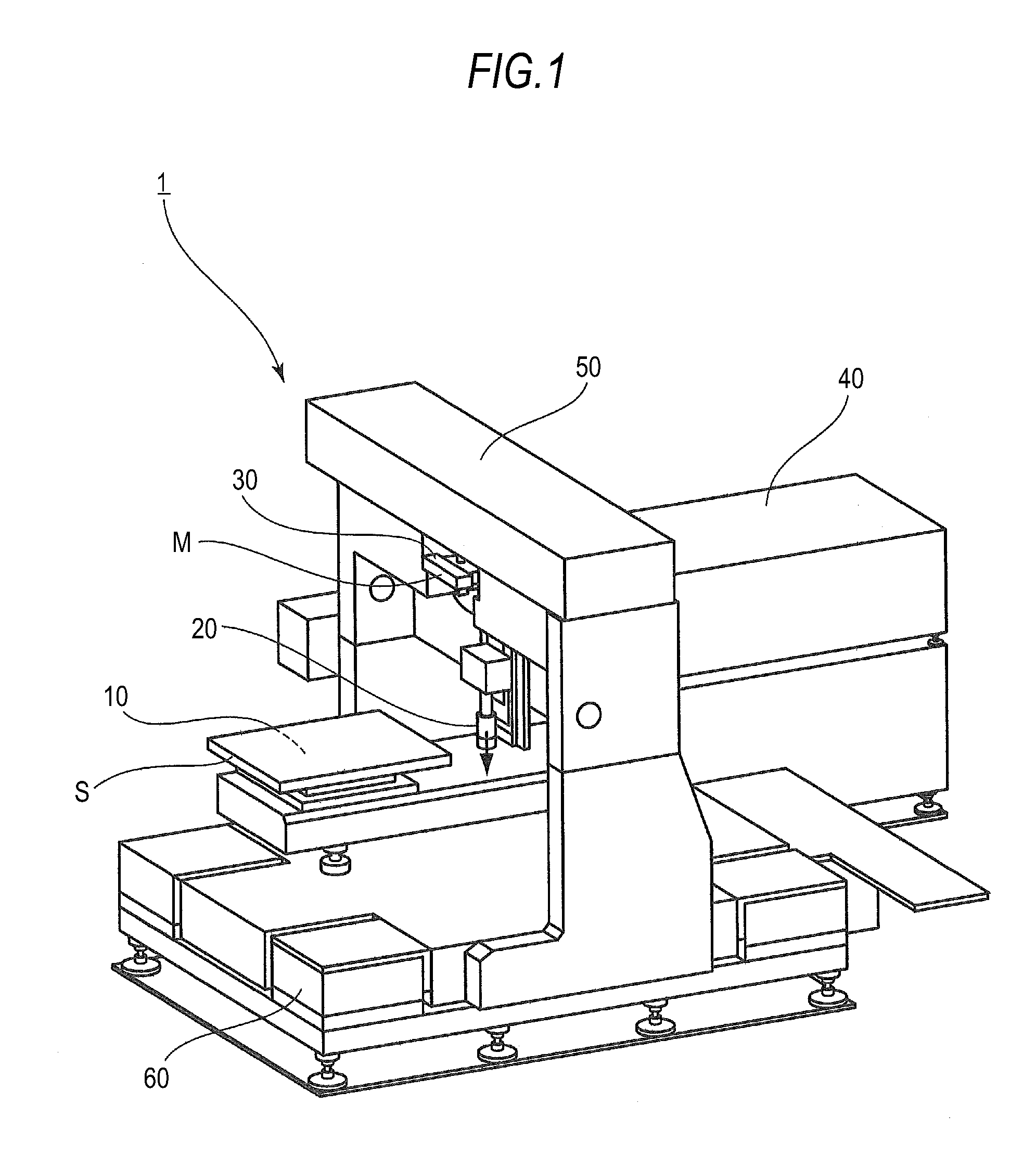
Image

  • Optical processing method and mask
  • Optical processing method and mask
  • Optical processing method and mask

Examples


example 1

[0116]FIG. 11 is a plan view used to describe another example of the mask configuration (Example 1) according to the embodiment of the present invention. Herein, the vertical direction in the drawing is the width direction of the mask M and the horizontal direction in the drawing is the scanning direction of the light irradiation region via the mask M.

[0117]The mask M includes an opening forming region R in which a plurality of openings m1 are aligned vertically and horizontally. In the opening forming region R, there are a first region R1 and a second region R2 provided, respectively, on one side and on the other side of the central axis along the scanning direction. The first region R1 and the second region R2 are line symmetric with respect to the central axis.

[0118]With the mask M configured as above, irradiation lines corresponding to the first region R1 and those corresponding to the second region R2 are superimposed in an irradiation region in a given stage by irradiation acr...

example 2

[0119]FIG. 12 is a plan view used to describe still another example of the mask configuration (Example 2) according to the embodiment of the present invention. Herein, the vertical direction in the drawing is the width direction of the mask M and the horizontal direction in the drawing is the scanning direction of the light irradiation region via the mask M.

[0120]The mask M has a first region R1 and a second region R2, respectively, on one side and on the other side of the central axis along the scanning direction. Accordingly, the mask M as a whole has an opening forming region R of a rhombic shape.

[0121]Even with the mask M having the opening forming region R of a rhombic shape as above, irradiation lines corresponding to the first region R1 and those corresponding to the second region R2 are superimposed in the irradiation region in a given stage by irradiation across one width of the mask M and the irradiation region in the following stage. Because a light irradiation amount in ...

example 3

[0122]FIG. 13 is a plan view used to describe still another example of the mask configuration (Example 3) according to the embodiment of the present invention. Herein, the vertical direction in the drawing is the width direction of the mask M and the horizontal direction in the drawing is the scanning direction of the light irradiation region via the mask M.

[0123]The mask M has an opening forming region R in which a plurality of openings m1 are aligned vertically and horizontally. In the opening forming region R, there are a first region R1 and a second region R2 provided, respectively, on one side and on the other side of the central axis along the scanning direction.

[0124]The first region R1 is of a trapezoidal shape and a plurality of openings m1 along the width direction of the mask M are provided in such a manner the number thereof varies in part of the lines. Meanwhile, the second region R2 is of a triangular shape. Herein, a missing portion of the trapezoidal shape correspond...


PUM

PropertyMeasurementUnit
widthaaaaaaaaaa
shapeaaaaaaaaaa
angleaaaaaaaaaa

Abstract

An optical processing method includes the steps of: moving an irradiation region of light in a direction orthogonal to a width direction of a mask having openings aligned in the width direction while irradiating the light to a processing object via the mask; and when irradiating light across one width of the mask and moving the irradiation region in a latter stage after irradiation of light across one width of the mask and movement of the irradiation region in a former stage end, superimposing a part of a light irradiation portion by the irradiation of light across one width of the mask and the movement in the former stage and a part of a light irradiation portion by the irradiation of light across one width of the mask and the movement in the latter stage to make an irradiation amount equal in each irradiation line corresponding to the respective openings.

Description

BACKGROUND OF THE INVENTION[0001]1. Field of the Invention[0002]The present invention relates to an optical processing method and a mask, and more particularly, to an optical processing method of forming a 3D shape in a processing object with energy of irradiated light by moving an irradiation region while irradiating light onto the processing object via a mask and a mask.[0003]2. Description of the Related Art[0004]As a method of processing a 3D shape using energy of light, there is a method of directly molding a shape of a processing object without using photolithography. Examples of such a processing method include a laser processing method using an excimer laser as is disclosed, for example, in JP-A-2004-160518. More specifically, an excimer laser has photon energy high enough to cut a chemical bonding and is therefore capable of removing a material from a processing object by a photochemical reaction called ablation while suppressing thermal influences.[0005]Such laser processi...

Claims


Application Information

Patent Timeline
Patent Type & Authority Applications(United States)
IPC IPC(8): B29C35/08G21K1/00B23K26/00B23K26/06B23K26/36
CPCB23K26/0656B23K26/408B23K26/4065B23K26/362B23K26/361B23K26/066B23K26/40B23K2103/42B23K2103/50B23K2103/52
Inventor JOZAKI, TOMOHIDEMATSUI, SHUNSUKENANASE, SHINGOMURASE, HIDEHISA
Owner SONY CORP
Features
  • R&D
  • Intellectual Property
  • Life Sciences
  • Materials
  • Tech Scout
  • Unparalleled Data Quality
  • Higher Quality Content
  • 60% Fewer Hallucinations
Learn More