Injection-molded stator

a stator and injection molding technology, applied in the field of stators, can solve the problems of easy corrosion or oxidation of the head, complex processing of the seal housing, and great inconvenience in installation, and achieve the effects of convenient and easy sealing processing, not easy to detach, and convenient head finding

Active Publication Date: 2010-09-09
ZHONGSHAN BROAD OCEAN
View PDF6 Cites 2 Cited by
  • Summary
  • Abstract
  • Description
  • Claims
  • Application Information

AI Technical Summary

Benefits of technology

[0007]In view of the above-described problem, it is one objective of the invention to provide an injection-molded motor in which a connector is conveniently installed, firmly fixed, orderly distributed and not easily corroded or oxidized, and features simple processing and good sealing effect.
[0026]Advantages of the invention comprise: 1) the second groove and the first outlet make sealing processing convenient and easy; 2) the third groove and the second outlet prevent the sealant from flowing out and ensure the connector is fully sealed by the sealant; 3) structure of the first groove ensures the connector to be firmly fixed and not easily detached; 4) the first cylinder makes it convenient to find the head of the coil winding when the head is connected to the power lead; 5) the hook makes it convenient to wrap the head of the coil winding on the first cylinder; 6) the fourth groove prevents erroneous winding and makes it convenient for operating and testing; 7) a wide variety of materials can be used to make the coil winding; 8) the chin portion penetrates enamel leather of the coil winding and simplifies the production process; 9) the screw and the elastic sleeve are tightly fit with each other, and thus ensuring convenient installation, accurate positioning and good shock absorbing effect, bearing axial locking force, and preventing the end insulating plate from deforming or breaking.

Problems solved by technology

However, there are several problems with the structure: the connector is unfixed and disorderly distributed in the motor, which causes great inconvenience for installation; the unfixed connector often randomly swings in the motor, and safety of the motor cannot be ensured; the unfixed connector is easily detached; finally, the head is easily corroded or oxidized by tin if the head of the coil winding is connected to the power lead via tin soldering.
But processing of the seal housing is complex, and sealing effect thereof is not good enough.

Method used


Image

  • Injection-molded stator
  • Injection-molded stator
  • Injection-molded stator

Examples


Embodiment Construction

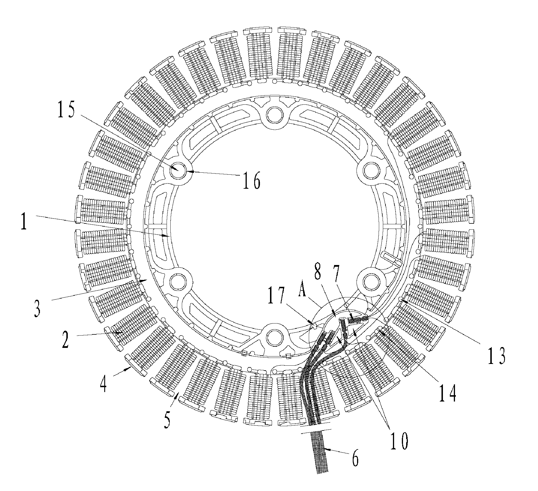
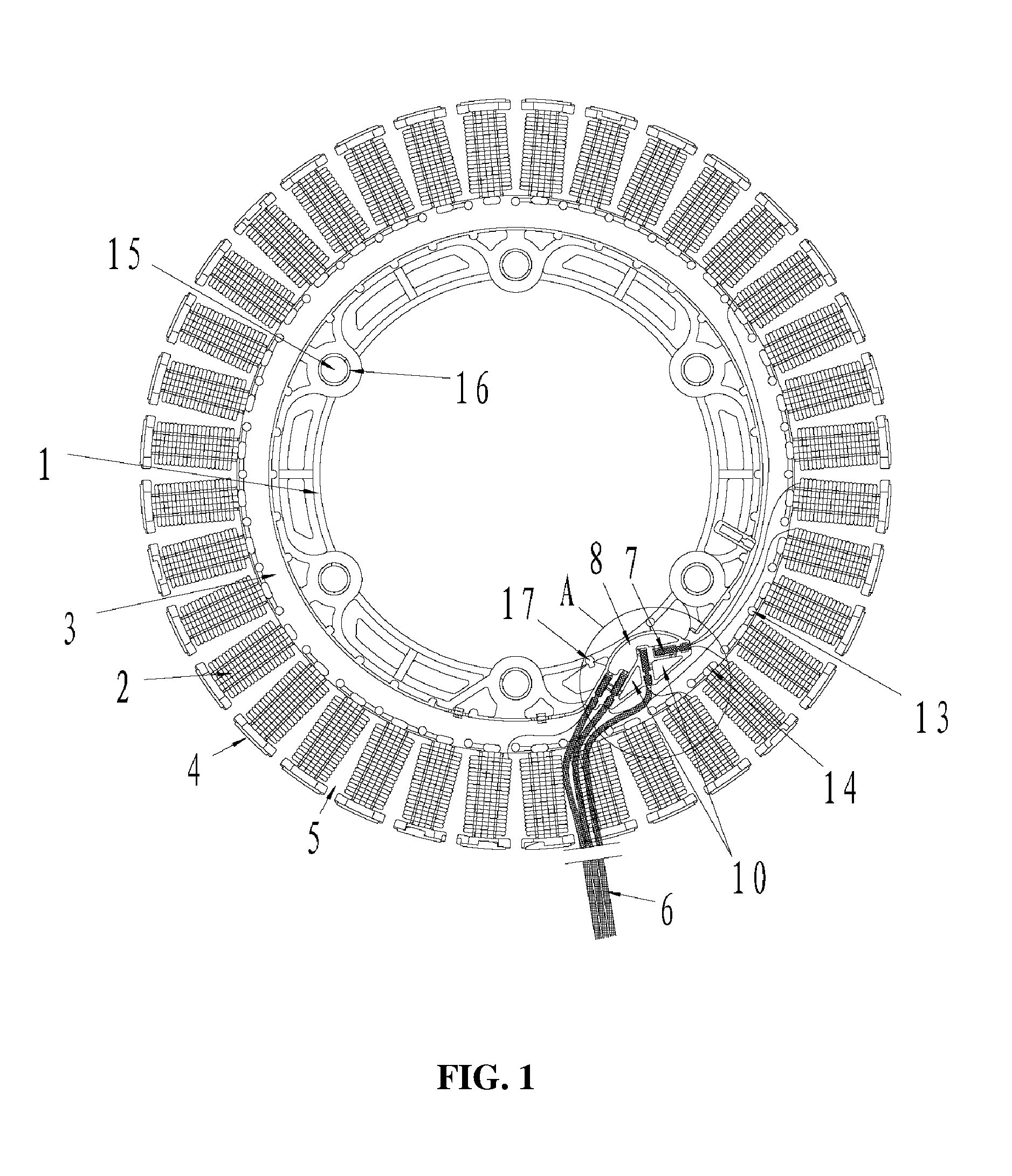
[0032]As shown in FIGS. 1-4, an injection-molded stator of the invention comprises a stator core 1, a coil winding 2 having a head, an end insulating plate 3, and a connector 7.

[0033]In this embodiment, the coil winding 2 is an enameled copper coil or an enameled aluminum coil.

[0034]The end insulating plate 3 is disposed on one end of the stator core 1.

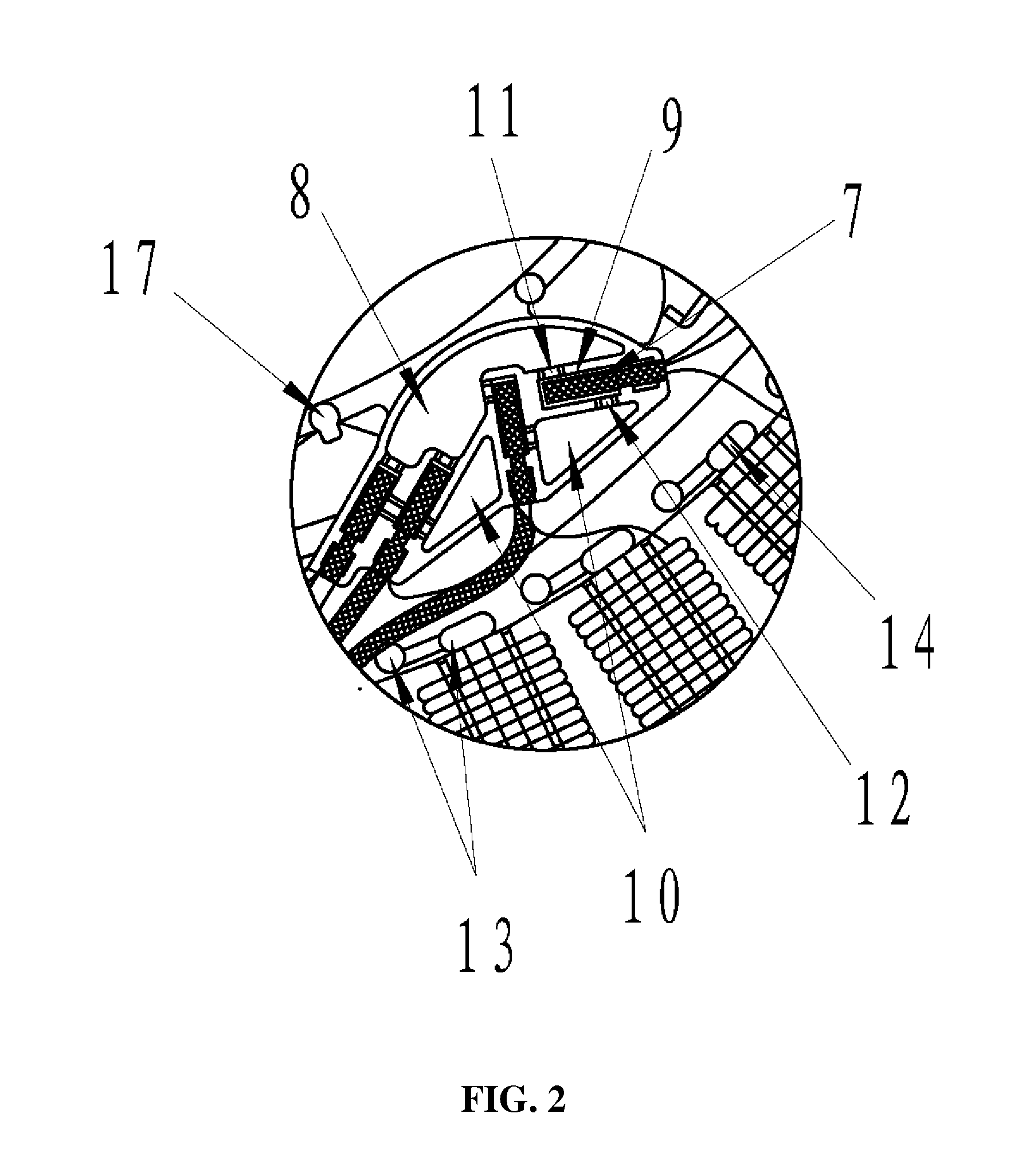
[0035]A first groove 9, a second groove 8 and a third groove 10 are disposed on the end insulating plate 3.

[0036]The connector 7 is formed by the head of the coil winding 2 and a power lead 6 electrically connected to each other, and the connector 7 is fixed in the first groove 9 via sealant.

[0037]A first outlet 11 is disposed between the first groove 9 and the second groove 8.

[0038]A second outlet 12 is disposed between the first groove 9 and the third groove 10.

[0039]The sealant is injected from the second groove 8 and flows into the first groove 9 via the first outlet 11, whereby fixing the connector 7 in the first groove 9.

[0040]R...


PUM


Abstract

An injection-molded stator has a stator core, a coil winding having a head, an end insulating plate having a first groove, and a connector. The end insulating plate is disposed on one end of the stator core, the connector is formed by the head of the coil winding and a power lead electrically connected to each other, and the connector is fixed in the first groove via sealant. The connector is conveniently installed, firmly fixed, orderly distributed and not easily corroded or oxidized, and features simple processing and good sealing effect.

Description

CROSS-REFERENCE TO RELATED APPLICATIONS[0001]Pursuant to 35 U.S.C. §119 and the Paris Convention Treaty, this application claims the benefit of Chinese Patent Application No. 200910037761.3 filed on Mar. 5, 2009, the contents of which are incorporated herein by reference.BACKGROUND OF THE INVENTION[0002]1. Field of the Invention[0003]The invention relates to a stator, and more particularly to an injection-molded stator.[0004]2. Description of the Related Art[0005]In a conventional motor, a connector is formed by a head of a coil winding and a power lead electrically connected to each other via tin soldering or a terminal, and usually disposed inside the motor. However, there are several problems with the structure: the connector is unfixed and disorderly distributed in the motor, which causes great inconvenience for installation; the unfixed connector often randomly swings in the motor, and safety of the motor cannot be ensured; the unfixed connector is easily detached; finally, the...

Claims


Application Information

Patent Timeline
Patent Type & Authority Applications(United States)
IPC IPC(8): H02K1/04H02K11/00
CPCH02K15/12H02K3/522
Inventor ZHANG, XU
Owner ZHONGSHAN BROAD OCEAN
Why Eureka
Try Eureka