Off-axis fiber optic slip ring

a fiber optic and slip ring technology, applied in the field of off-axis multi-channel fiber optic slip ring, can solve the problems of almost no way to handle and arrange so many fibers on the said rotatable members, optical loss is very obvious for multi-mode fibers, and it is almost impossible to use single-mode fibers

Active Publication Date: 2010-09-09
PRINCETEL
View PDF1 Cites 54 Cited by
  • Summary
  • Abstract
  • Description
  • Claims
  • Application Information

AI Technical Summary

Benefits of technology

[0013]The object of the present invention is to eliminate the huge number of fiber bundles and photodiodes in most prior arts, to provide a true passive, bidirectional, no time jitter, low-loss off-axis optic slip ring which could be used for both multi-mode and single mode fibers.

Problems solved by technology

But actually, it is almost no way to handle and arrange so many fibers on the said rotatable members, especially for large diameter slip ring.
The optical loss is very obvious for multi-mode fibers.
It is almost impossible to use single mode fibers.
The effect of damaged fibers, the presence of debris, separation distances, component tolerances, or backlash in the gearing also cause problems.
The multiple inputs and pick-ups also cause a rapid rise and fall of the signal because the signal reflects from one area of the waveguide to another.
The drawback is to use photodiode receivers which is an electro-optical device, so that the output signal is electrical and the power must be high.
Besides, there is a time jitter thus limiting the data rate.

Method used


Image

  • Off-axis fiber optic slip ring
  • Off-axis fiber optic slip ring
  • Off-axis fiber optic slip ring

Examples


Embodiment Construction

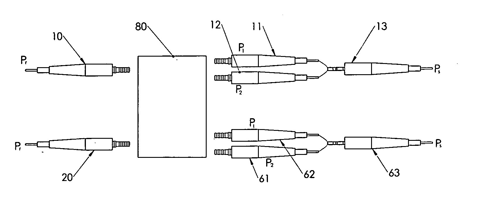
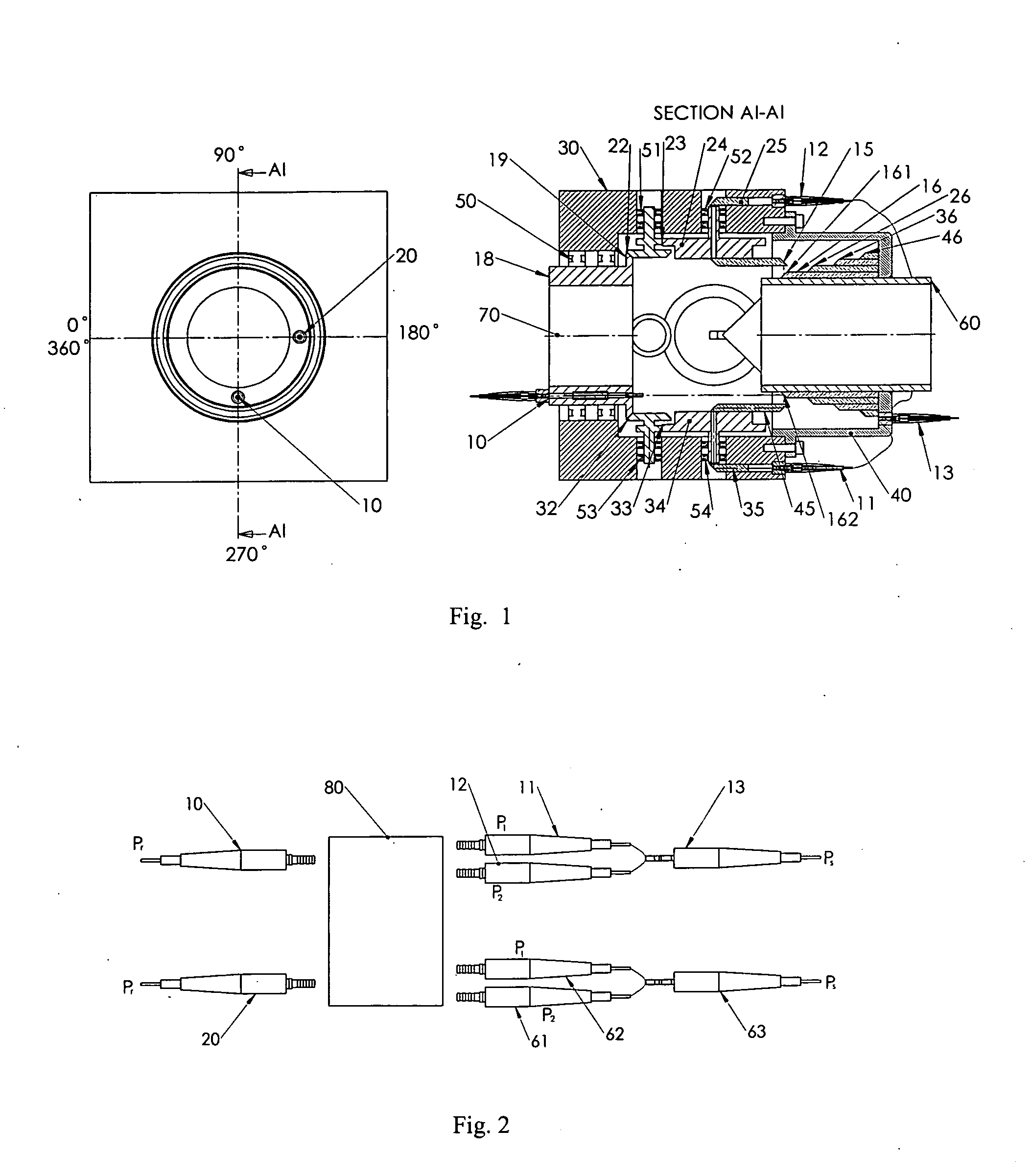
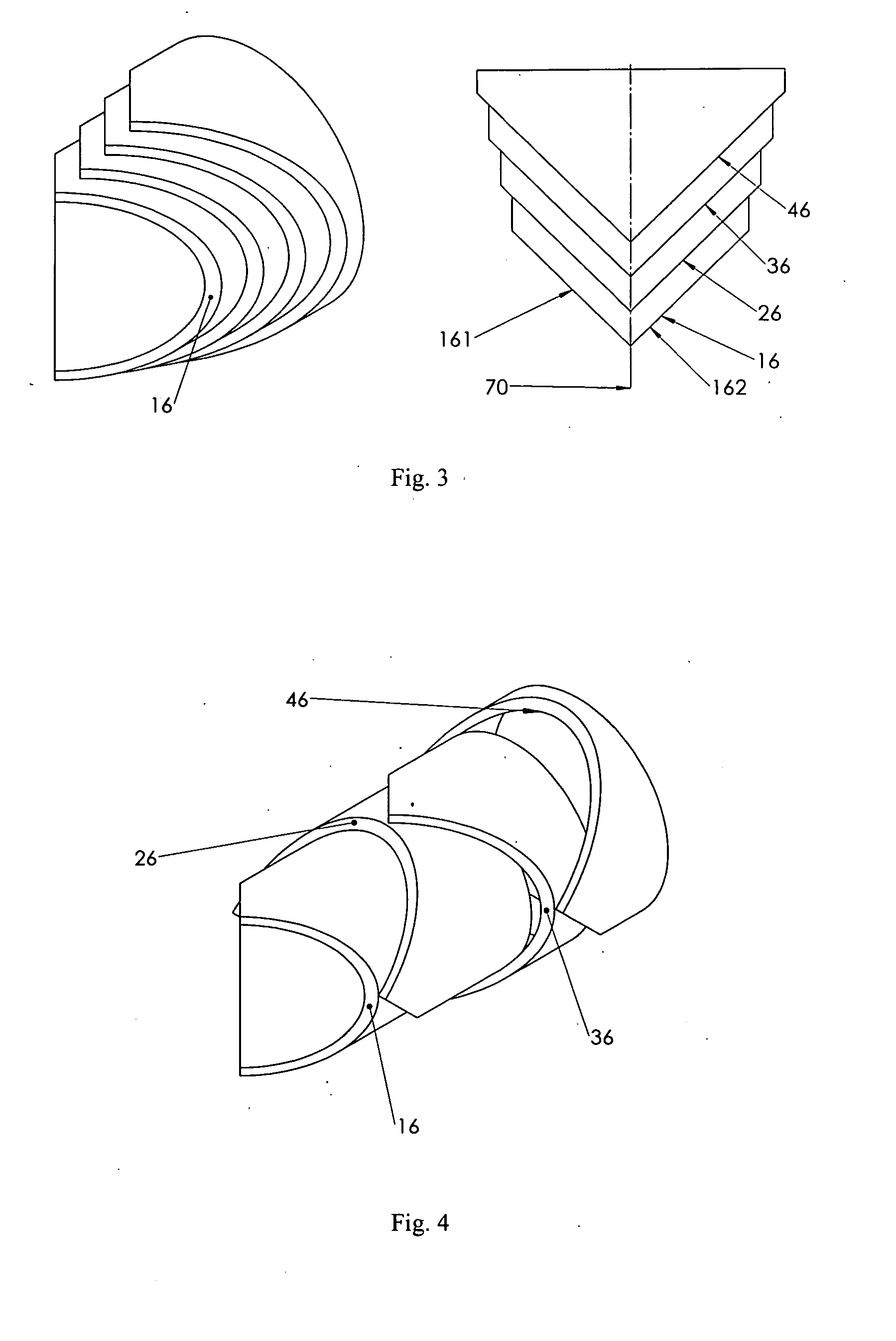
[0022]As shown in FIG. 1, a typical embodiment of a multi-channel off-axis optic slip ring in the present invention comprises rotor 18, stator 30, mirror array 16, 26, 36, 46, rhomboid prisms 15, 45, right angle prisms 25,35, gears 19,22, 23,24, collimators 10,20,11,12, and coupler 13. A pair of bearings 50 are mounted between rotor 18 and stator 30 to provide the main rotational interface. Other bearings 51, 52, 53, and 54 are used to rotationally support the gears 22, 23, 24; 32, 33, and 34 in the stator 30. Collimators 10, 20, and more (depends on how many channel would be built), are mounted on rotor 18 in circumferential direction at a different distances to the common rotational axis 70. The axis of the collimators 10, and 20 are parallel to the main rotational axis 70. The rotor 18 and the mirror holder 60 are hollow along the said common rotational axis so that a through bore is provided, leaving the central part of the interface totally free. That means all the optical sign...


PUM


Abstract

A multi-channel off-axis optic slip ring system is disclosed. The invention eliminates the huge number of fiber bundles and photodiodes in most published patents. A couple of conventional optical components such as mirrors and prisms are used to transmit optical signals with high quality and low optic losses. The optical signal pick-up is realized through a pair of prisms mounted on gear transmission systems. It is a true passive, bi-directional rotational optical transmission device which could be used for both multi-mode and single mode fibers without the limitation to the through bore diameters.

Description

REFERENCES CITED[0001]U.S. PATENT DOCUMENTS4,460,242July 1984Birch, et al.4,492,427January 1985Lewis, et al.4,943,137July 1990Speer4,934,783June 1990Jacobson6,907,161July 2005BowmanOTHER PUBLICATIONS[0002]“Fiber Optic Rotary Joints-A Review”, by GLENN F. I. DORSEY. IEEE Trans. Components, Hybrids, and Manufac. Technol., vol. CHMT-5, NO. 1, 1982, PP 39.[0003]“Mechanism design, analysis and synthesis, volume 1” by Arthur G. Erdman and George N. Sandor. Third Edition. 1997.BACKGROUND OF THE INVENTION[0004]1. Field of the Invention[0005]The invention is related to off-axis multi-channel fiber optic slip ring to provide transmission of data in optic form between a mechanically rotational interface with a through bore.[0006]2. Description of Related Art[0007]It is well known that the devices to transmit optical data between two independently rotational members are called fiber optical rotary joints, or optical slip ring. There are single channel, two channel and multi-channel fiber optica...

Claims


Application Information

Patent Timeline
Patent Type & Authority Applications(United States)
IPC IPC(8): G02B6/42
CPCG02B6/3604
Inventor ZHANG, HONGZHANG, BOYING B.
Owner PRINCETEL
Why Eureka
Try Eureka