[0011]The present invention has been made in light of this circumstance, and it is an object thereof to provide a reservoir tank, and a
brake device using the reservoir tank, with which the volume of an
air chamber above hydraulic fluid can be increased without changing the height of a hydraulic fluid supply opening from a MAX line.
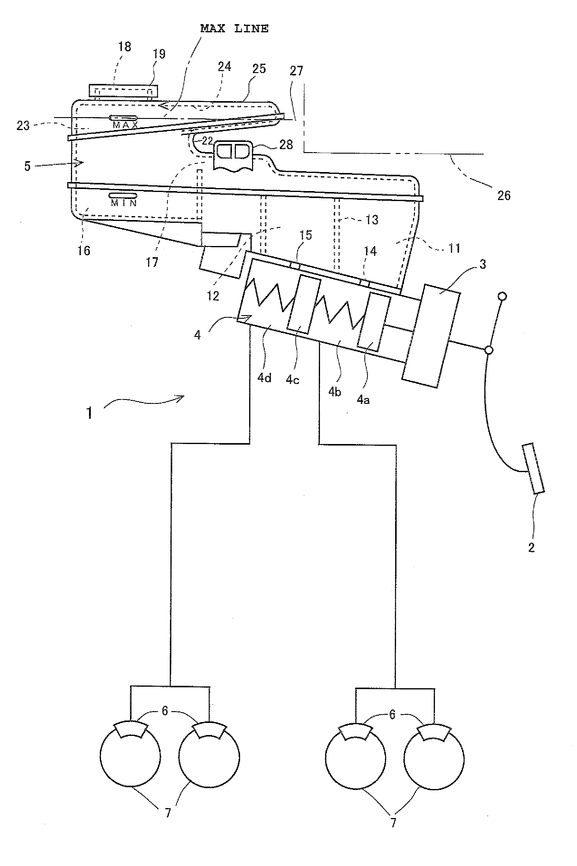
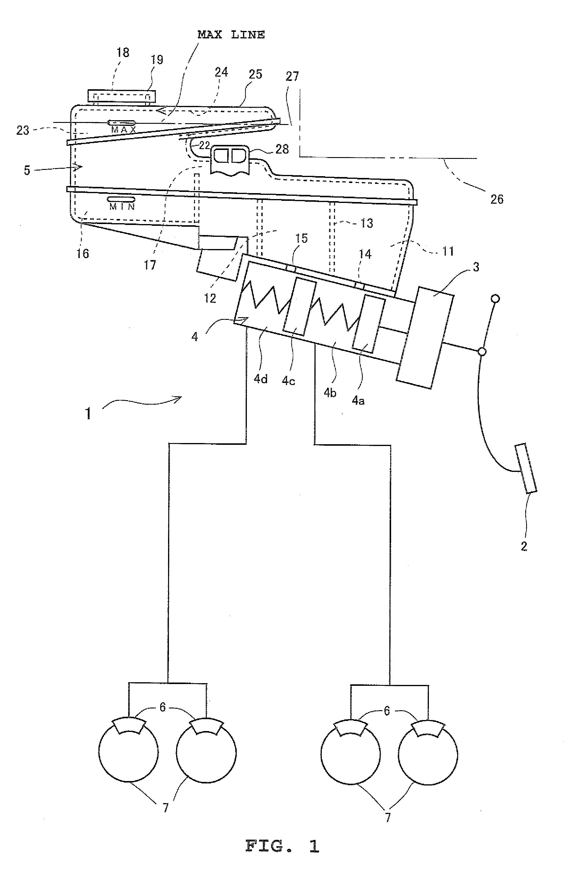
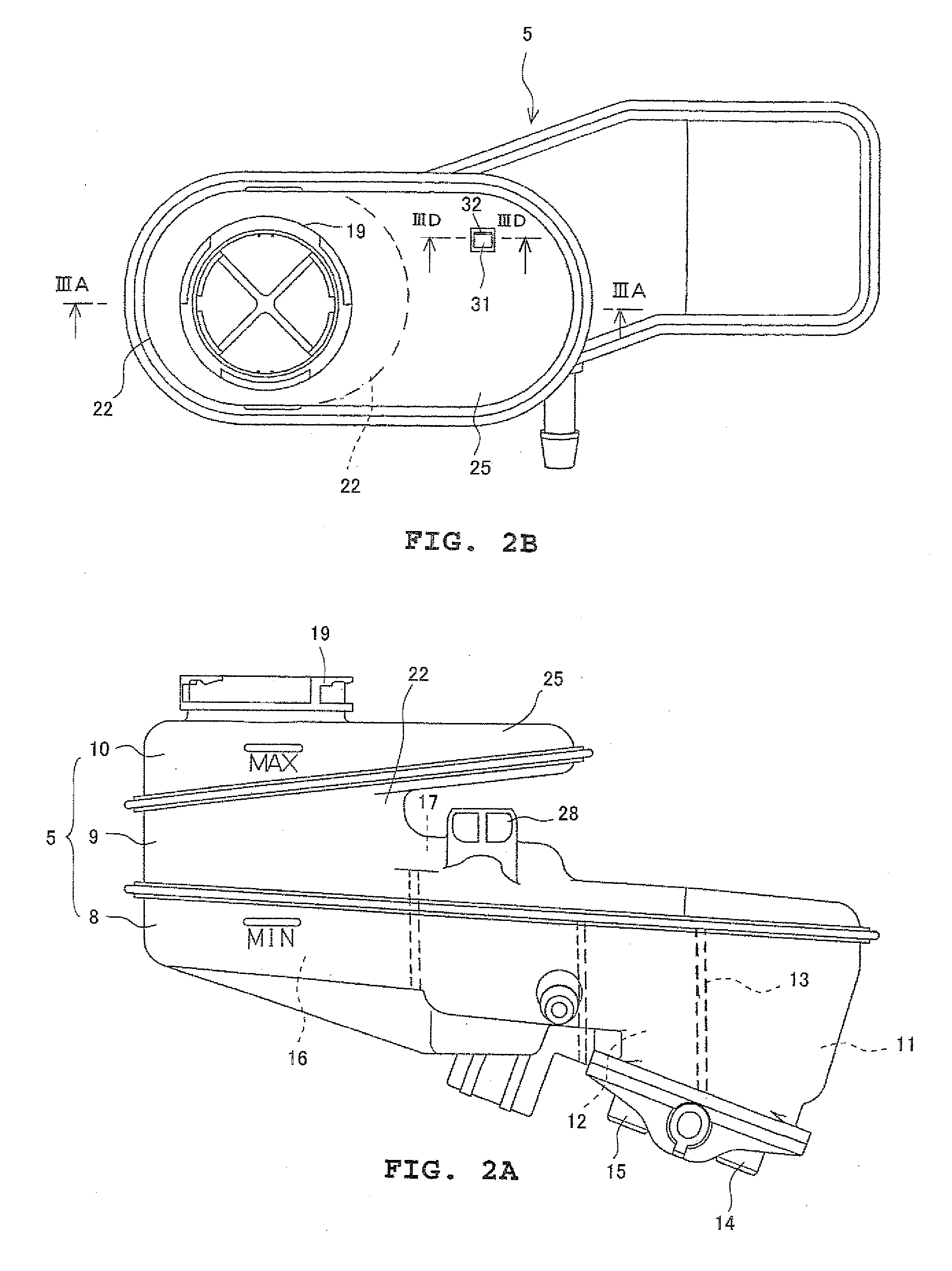
[0018]According to the reservoir tank of the present invention configured in this manner, the volume-augmented chamber forming portion that has inside the volume-augmented chamber that is communicated with the chamber of the cylindrical portion is disposed in the cylindrical portion that is disposed between the hydraulic fluid supply opening and the hydraulic fluid supply portion, to which the hydraulic fluid is supplied from this hydraulic fluid supply opening and which supplies this hydraulic fluid to the hydraulic fluid storage chamber, and has the chamber that is communicated with the hydraulic fluid supply portion, and at least part of this volume-augmented chamber is positioned above the MAX line of the hydraulic fluid. Thus, in a state where the hydraulic fluid fills the reservoir tank to the MAX line, a new
air chamber can be formed inside at least part of the volume-augmented chamber in addition to the
air chamber that is formed inside the cylindrical portion. Consequently, when the temperature of the hydraulic fluid rises and the volume of the hydraulic fluid increases because of the use environment described above, this increased
volume change in the hydraulic fluid can be absorbed by the conventional air chamber and can also be absorbed by the new air chamber. As a result, even when the increase change in the volume of the hydraulic fluid is relatively large, the increase change in the volume of the hydraulic fluid can be more reliably absorbed, and a situation where the hydraulic fluid leaks out to the outside from the hydraulic fluid supply opening can be suppressed.
[0019]Further, according to the reservoir tank of the present invention, the volume-augmented chamber forming portion is disposed so as to extend horizontally or substantially horizontally from the cylindrical portion, so even when the volume-augmented chamber forming portion is disposed, the distance between the hydraulic fluid supply opening and the MAX line can be set to be the same as in a conventional reservoir used in a vehicle in which the reservoir tank of the present invention is used. Thus, as a pressure-feed filling device instrument that fills the inside of the reservoir tank with the hydraulic fluid, a conventional pressure-feed filling device instrument can be used as is, so that the pressure-feed filling device instrument does not have to be changed. Consequently, the number of types of pressure-feed filling device instruments does not increase by that amount, so when the vehicle
production line is a line that continuously produces different vehicle types, various types of pressure-feed filling device instruments do not have to be prepared for the production line even when the reservoir tank having the volume-augmented chamber forming portion is used. As a result, the work of filling the reservoir tank with the hydraulic fluid becomes simple and instrument misuse can be suppressed.
[0020]Moreover, according to the reservoir tank of the present invention, the volume-augmented chamber forming portion is disposed so as to extend horizontally or substantially horizontally from the cylindrical portion and into the
dead space when the reservoir tank is installed in a vehicle, so even when the volume-augmented chamber forming portion is disposed, the reservoir tank can be efficiently installed in the limited space of a relatively narrow
engine room without interfering with other parts. In particular, the volume-augmented chamber forming portion is disposed so as to extend above the hydraulic fluid passage positioned between the hydraulic fluid supply portion and the hydraulic fluid storage chamber. The space above this hydraulic fluid passage becomes
dead space, so the entire reservoir tank can be formed in substantially the same size as that of a conventional reservoir tank even when the volume-augmented chamber forming portion is disposed, and an increase in the size of the reservoir tank can be suppressed. Consequently, the reservoir tank can be even more efficiently installed in the limited space of the
engine room.
[0021]Moreover, according to the reservoir tank of the present invention, the bottom portion of the volume-augmented chamber slants so as to become a downward slope toward the chamber inside the cylindrical portion. Thus, it becomes possible to more reliably cause the hydraulic fluid entering the inside of the volume-augmented chamber to flow toward the chamber—that is, the hydraulic fluid supply portion—when the quantity of the hydraulic fluid inside the reservoir tank decreases.
[0022]According to the
brake device equipped with the reservoir tank of the present invention, even in a vehicle where the temperature of the
engine room becomes relatively high, by using the reservoir tank of the present invention in the brake device, leakage of the
brake fluid that is the hydraulic fluid from the hydraulic fluid supply opening can be suppressed so that the brakes can be more reliably actuated, and
contamination inside the engine room can be prevented.


