Multiple actuating-force shearing machine

a shearing machine and multi-actuating force technology, applied in the field of shearing, can solve the problems of large hydraulic fluid volume to be pumped for moving the shearing blades, inability to achieve the full width of the cut, etc., to achieve the effect of reducing the size of the hydraulic pump and valv

Inactive Publication Date: 2010-09-16
PRIMETALS TECH
View PDF12 Cites 7 Cited by
  • Summary
  • Abstract
  • Description
  • Claims
  • Application Information

AI Technical Summary

Benefits of technology

[0015]The object of the present invention is to provide a method of operating a hydraulic shearing machine with curved blade able to cut materials with a wide range of thickness, width and strength with sufficient throughputs, in which the required size of hydraulic pumps and valves is reduced, and to provide a hydraulic shearing machine for performing that method with a reduced size of the hydraulic pump and valves compared to the prior art.

Problems solved by technology

When shearing wide metal plates and strips, a straight cut of the full width of material would require an enormous overall actuating-force which would not be practical.
Consequently, the volume of hydraulic fluid to be pumped for moving the shear blades is large and has to be pumped quickly, which requires large hydraulic pumps and valves.
A hydraulic system with large pumps and valves is very expensive and needs a lot of space, and the operation of large pumps and valves is energy-intensive and high-maintenance.
However, for a hydraulic shearing machine with a curved blade the teaching of FR2212771 is not applicable, because to achieve a correct rocking type shearing action with a curved blade it is required that the movement of the two ends of the curved blade is controlled and synchronized precisely.

Method used


Image

  • Multiple actuating-force shearing machine
  • Multiple actuating-force shearing machine
  • Multiple actuating-force shearing machine

Examples


Embodiment Construction

[0016]That object is solved by a method for operating a hydraulic shearing machine comprising

[0017]for cutting a shearing-movement of at least one shear blade starting from a starting-position under application of an overall actuating-force, and

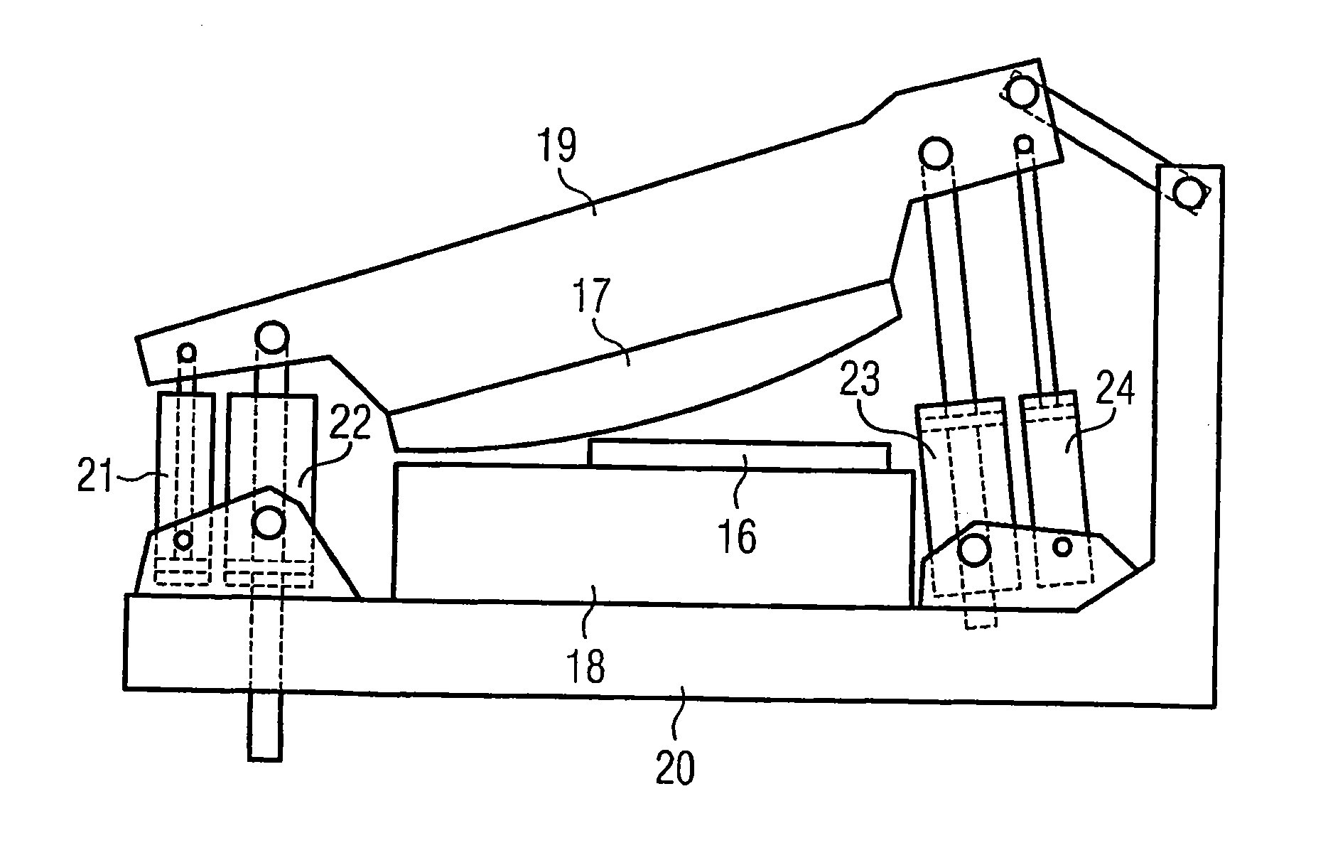
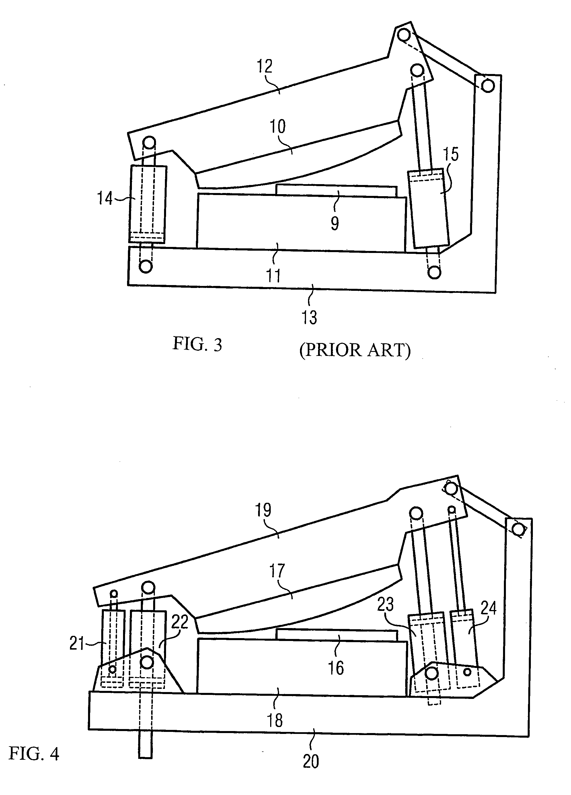
[0018]for resetting of the at least one shear blade which was moved for cutting to its starting-position after accomplishment of the shearing-movement a reset-movement under application of an overall reset-force, the shearing-movement and the reset-movement being accomplished by a hydraulic actuating-mechanism comprising hydraulic cylinders, and the overall actuating-force and the overall reset-force being applied to the at least one shear blade which is moved for cutting by at least two hydraulic cylinders of the actuating-mechanism, the magnitude of the overall actuating-force being adjustable by switching one or several hydraulic cylinders (21,22,23,24) of the actuating-mechanism in and out of operation-mode, characterized in that the cutt...


PUM

PropertyMeasurementUnit
rake angleaaaaaaaaaa
cutting cycle timeaaaaaaaaaa

Abstract

A method, and an apparatus, for operating a hydraulic shearing machine. For cutting a shearing-movement of at least one shear blade which is curved, starting from a starting-position under application of an overall actuating-force and for resetting of the shear blades which were moved for cutting to their starting-position after accomplishment of the shearing-movement, a reset-movement under application of an overall reset-force. The shearing-movement and the reset-movement are accomplished by a hydraulic actuating-mechanism comprising hydraulic cylinders, wherein the overall actuating-force and the overall reset-force being applied to the moved shear blades by at least one hydraulic cylinder of the actuating-mechanism. The magnitude of the overall actuating-force is adjustable by switching one or several hydraulic cylinders of the actuating-mechanism in and out of operation-mode. The method proposes that the positions of the curved shear blade are controlled by a control system by regulating the flow of hydraulic fluid to the hydraulic cylinders according to setpoints for a shear blade position versus time function and the overall actuating-force and overall reset-force requirements.

Description

CROSS REFERENCE TO RELATED APPLICATION[0001]The present application is a 35 U.S.C. §§371 national phase conversion of PCT / EP2008 / 007124, filed 1 Sep. 2008, which claims priority of European Application No. 07253538, filed 7 Sep. 2007, the disclosure of which is incorporated by reference herein. The PCT International Application was published in the English language.FIELD OF INVENTION[0002]The invention relates to the general field of shearing and in particular to the shearing of metal plates and strips.BACKGROUND OF THE INVENTION[0003]To perform a cut with a hydraulic shearing machine at least one shear blade has to be moved in the direction toward another shear blade with a force which is named overall actuating-force, that overall actuating-force being sufficient to overcome the resistance of the material to be cut, that resistance being named cutting force. When shearing wide metal plates and strips, a straight cut of the full width of material would require an enormous overall a...

Claims


Application Information

Patent Timeline
Patent Type & Authority Applications(United States)
IPC IPC(8): B23D15/14B26D5/12
CPCB23D15/14Y10T83/0605Y10T83/8788Y10T83/8798Y10T83/8827Y10T83/8854Y10T83/8864
Inventor CHRISTOFOROU, PETERCLARK, MICHAEL TREVOREASTWOOD, DAVIDSTONECLIFFE, DAVIDTYAS, SHAUN
Owner PRIMETALS TECH
Why Eureka
Try Eureka