Method and device for monitoring plasma discharges

a plasma discharge and monitoring device technology, applied in the direction of measurement devices, electric discharge tubes, instruments, etc., can solve the problems of high cost of reducing practice, known methods need quite a high cost in terms of measurement instruments and devices, and achieve the effect of low cos

Inactive Publication Date: 2010-09-16
SCHOTT AG
View PDF14 Cites 41 Cited by
  • Summary
  • Abstract
  • Description
  • Claims
  • Application Information

AI Technical Summary

Benefits of technology

[0006]Therefore, the object of the present invention is to provide a method and a device for monitoring plasma discharges which can preferably be realized simply and with low costs. In

Problems solved by technology

The OES-method, however, has the drawback that high expenses for reduction to practice are needed due to the operation of optoelectronic compo

Method used


Image

  • Method and device for monitoring plasma discharges
  • Method and device for monitoring plasma discharges
  • Method and device for monitoring plasma discharges

Examples


Embodiment Construction

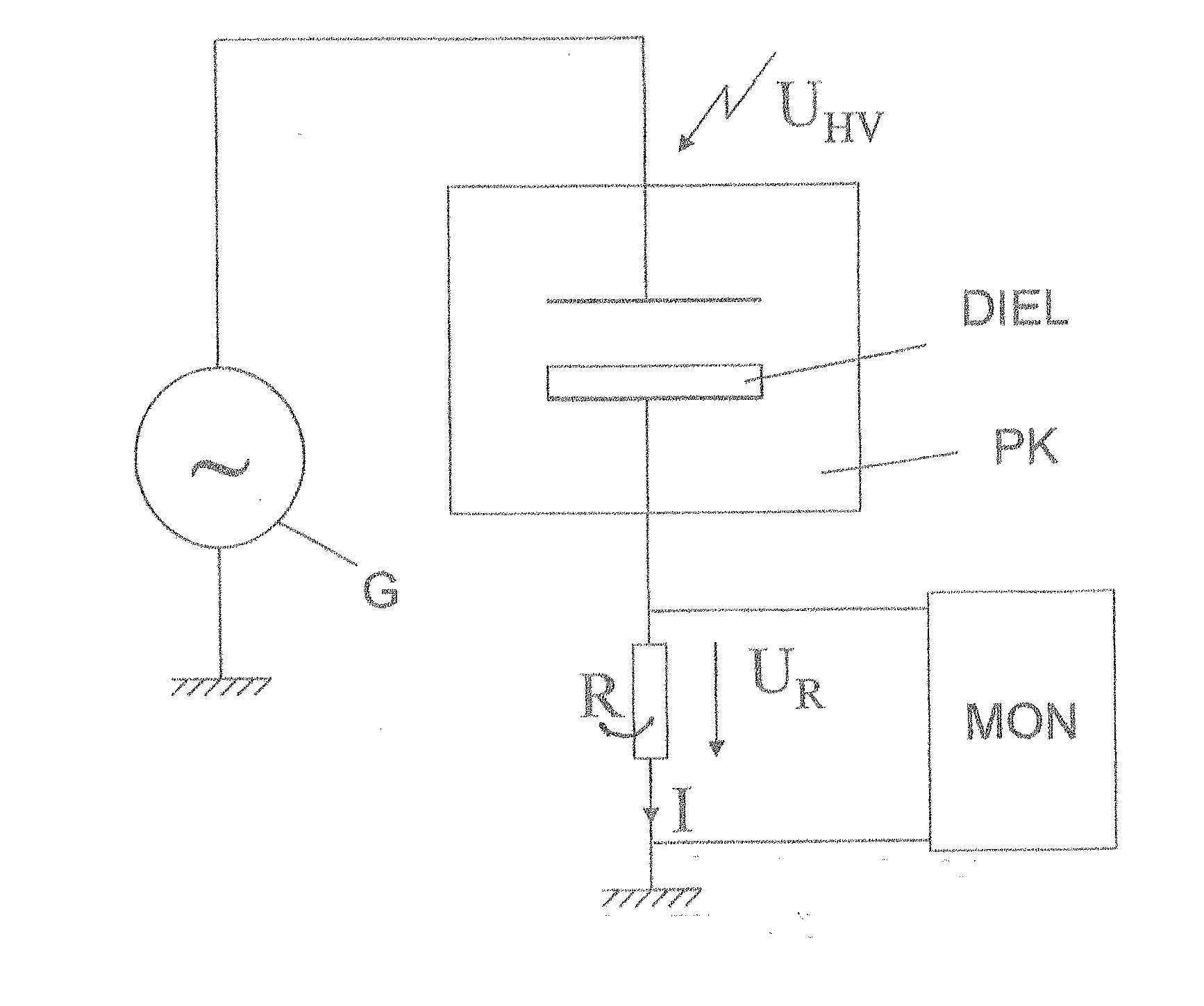
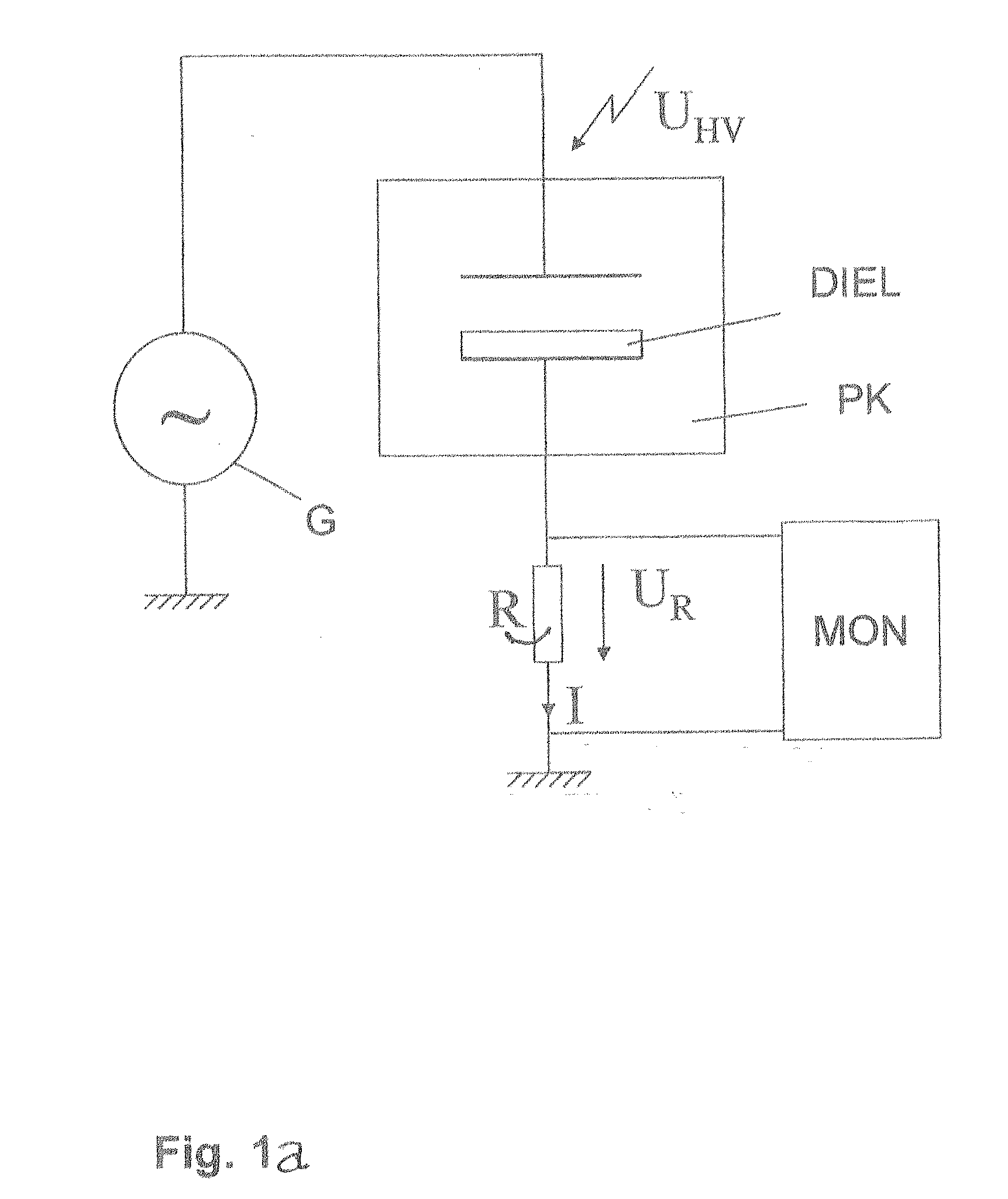
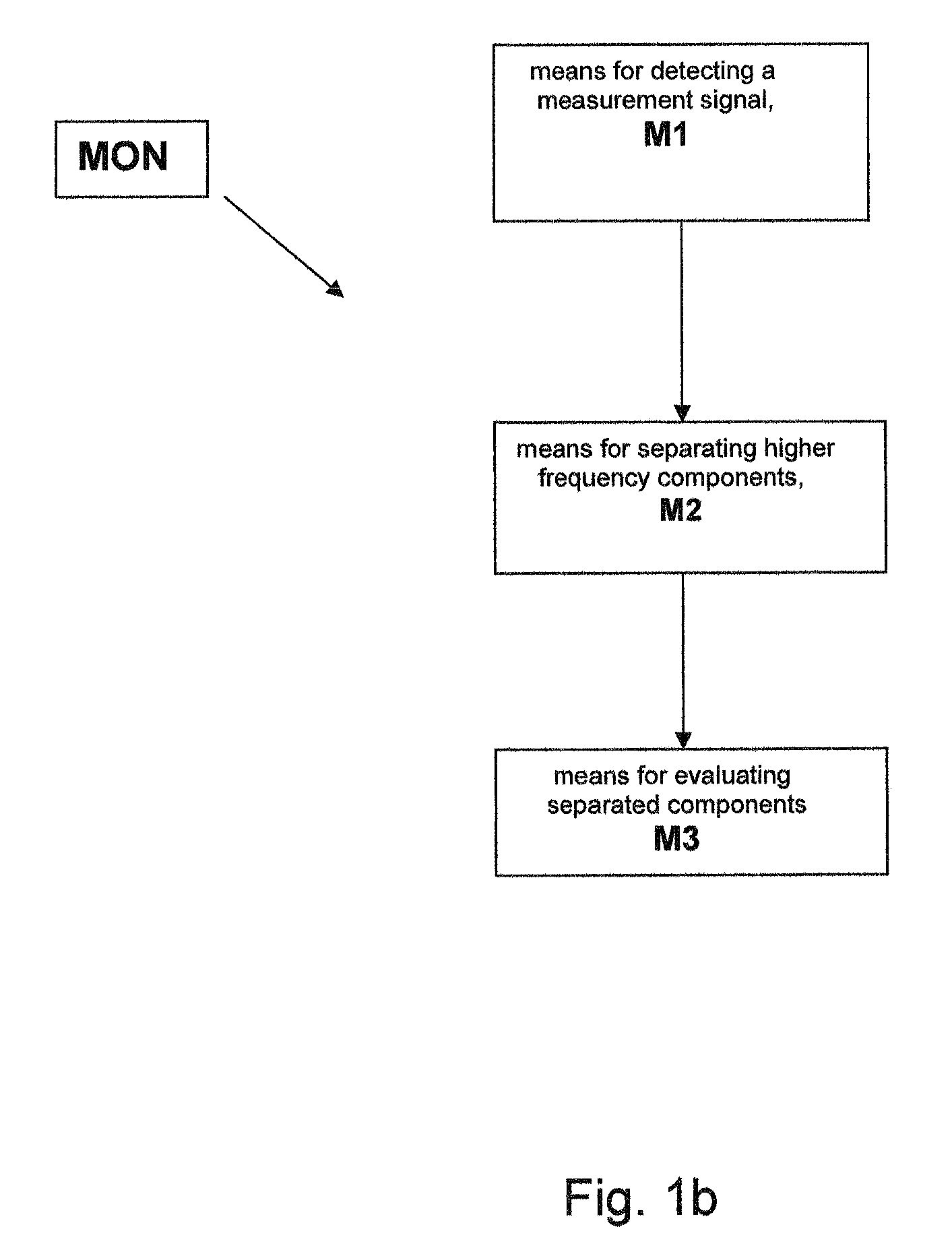
[0021]FIG. 1a is a circuit diagram of an electrical equivalent circuit of an arrangement or device for generating plasma by dielectric barrier discharge (DBD). In this equivalent circuit the arrangement has a capacitor comprising a dielectric DIEL, in which a dielectric displacement current I is generated when an electric alternating voltage UHV is applied. In this example, the generator G for example provides a sine-shaped alternating current UHV with an amplitude of 2 kV and a frequency of 15 kHz, which is applied to the electrodes within the plasma chamber PK. One of the electrodes is shielded by a dielectric (for example a glass plate) in order to avoid an ohmic short circuit. Thus, only the dielectric displacement current I is generated, which can be tapped at one of the conductors across the measuring resistor R as corresponding voltage drop UR and which can be supplied to a monitoring device MON for monitoring the plasma discharge, which is shown in more detail in FIG. 1b.

[0...


PUM


Abstract

A method and a device (MON) for monitoring plasma-discharges during a surface treatment process are described. In this process electrodes within a gaseous medium are provided with an alternating voltage (UHV) for generating plasma. The monitoring device (MON) has a detector device (M1) for detecting a measurement signal (I) generated by the alternating voltage (UHV) within the gaseous medium, separating means (M2) for separating signal components above a preset frequency and evaluating means (M3) for evaluating the resulting separated signal components by comparing them with at least one preset reference. Preferably the generating of the plasma is achieved by dielectric barrier discharge and the electric current penetrating the medium, especially the dielectric displacement current, is measured as the measurement signal (I).

Description

CROSS-REFERENCE[0001]The invention described and claimed herein below is also described in German Patent Application DE 10 2009 011 960.4, filed on Mar. 10, 2009 in Germany. The aforesaid German Patent Application, whose subject matter is incorporated herein by reference thereto, provides the basis for a claim of priority of invention for the invention claimed herein below under 35 U.S.C. 119 (a)-(d).BACKGROUND OF THE INVENTION[0002]The invention relates to a method and to a device for monitoring of plasma discharges. In particular, the invention relates to a method and to a device for monitoring plasma discharges (also called plasma ignition) during surface treatment processes in which electrodes in a gaseous medium are charged with an alternating voltage for generating the plasma. Among these there are, for example, methods by which plasma is generated for coating and modifying the surface of miscellaneous products, such as pharmaceutical packing material made of glass and / or plas...

Claims


Application Information

Patent Timeline
IPC IPC(8): G01R23/12
CPCH01J37/32036H01J37/32935H01J37/32348
Inventor BAUCH, HARTMUTBICKER, MATTHIAS
Owner SCHOTT AG
Why Eureka
Try Eureka