Method of improving the electrical conductivity of a conductive ink trace pattern and system therefor

Inactive Publication Date: 2010-09-16
WESTERN MICHIGAN UNIVERSITY
View PDF8 Cites 29 Cited by
  • Summary
  • Abstract
  • Description
  • Claims
  • Application Information

AI Technical Summary

Benefits of technology

[0004]The present invention provides a method and system of improving the conductivity of an electrically conductive ink trace fixed on a substrate by subjecting the substrate having the trace fixed thereto to a

Problems solved by technology

However, whatever method is used to print the electroconductive ink, there exists a common problem of poor ink transfer due to surface roughness and poor conductivity due to insufficient drying or curing to the ink film.
The ink having satisfa

Method used


Image

  • Method of improving the electrical conductivity of a conductive ink trace pattern and system therefor
  • Method of improving the electrical conductivity of a conductive ink trace pattern and system therefor
  • Method of improving the electrical conductivity of a conductive ink trace pattern and system therefor

Examples


Example

Example

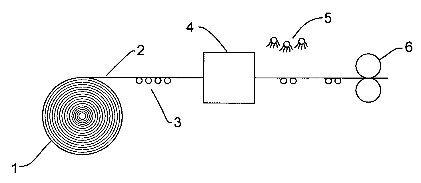
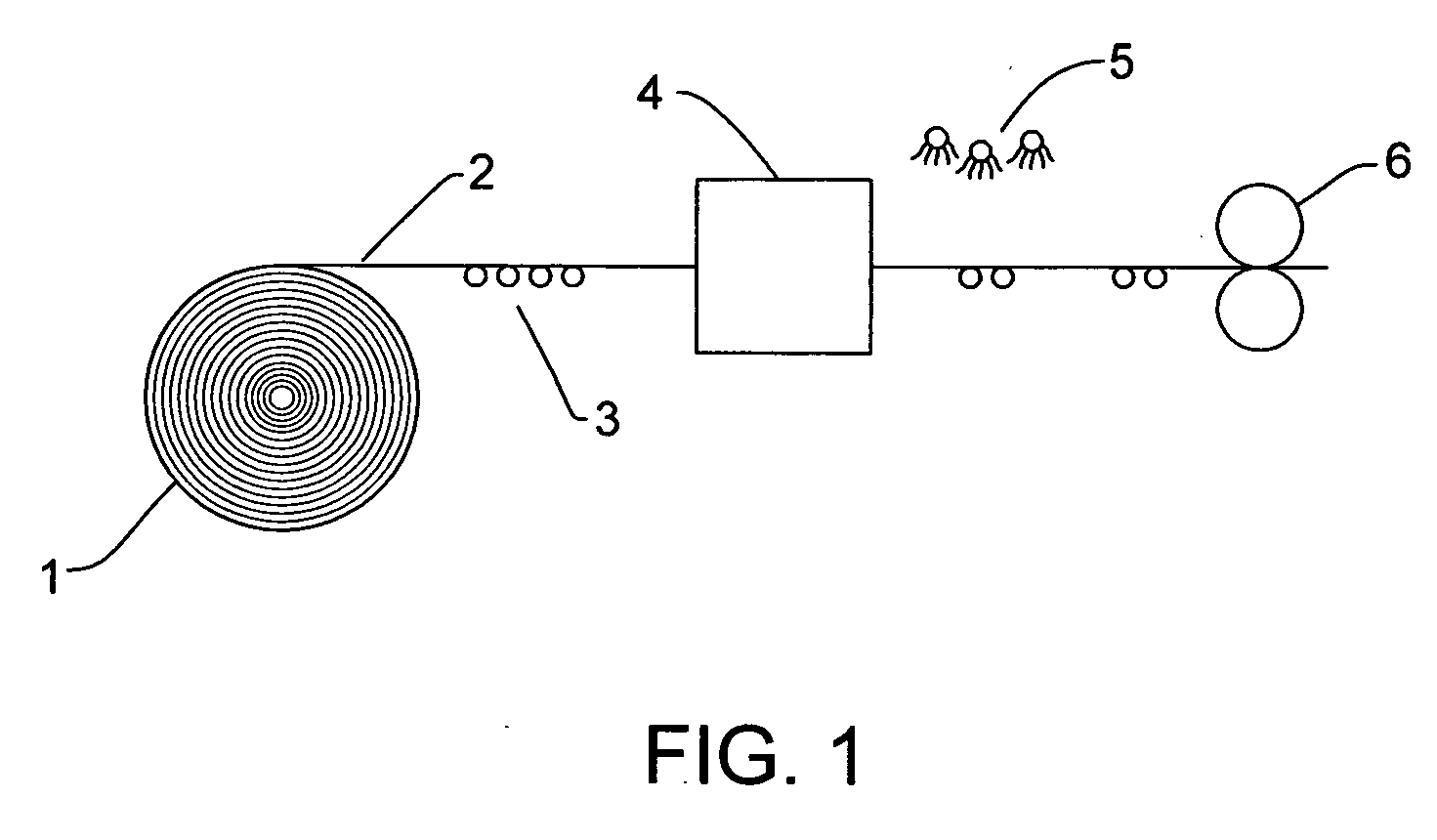
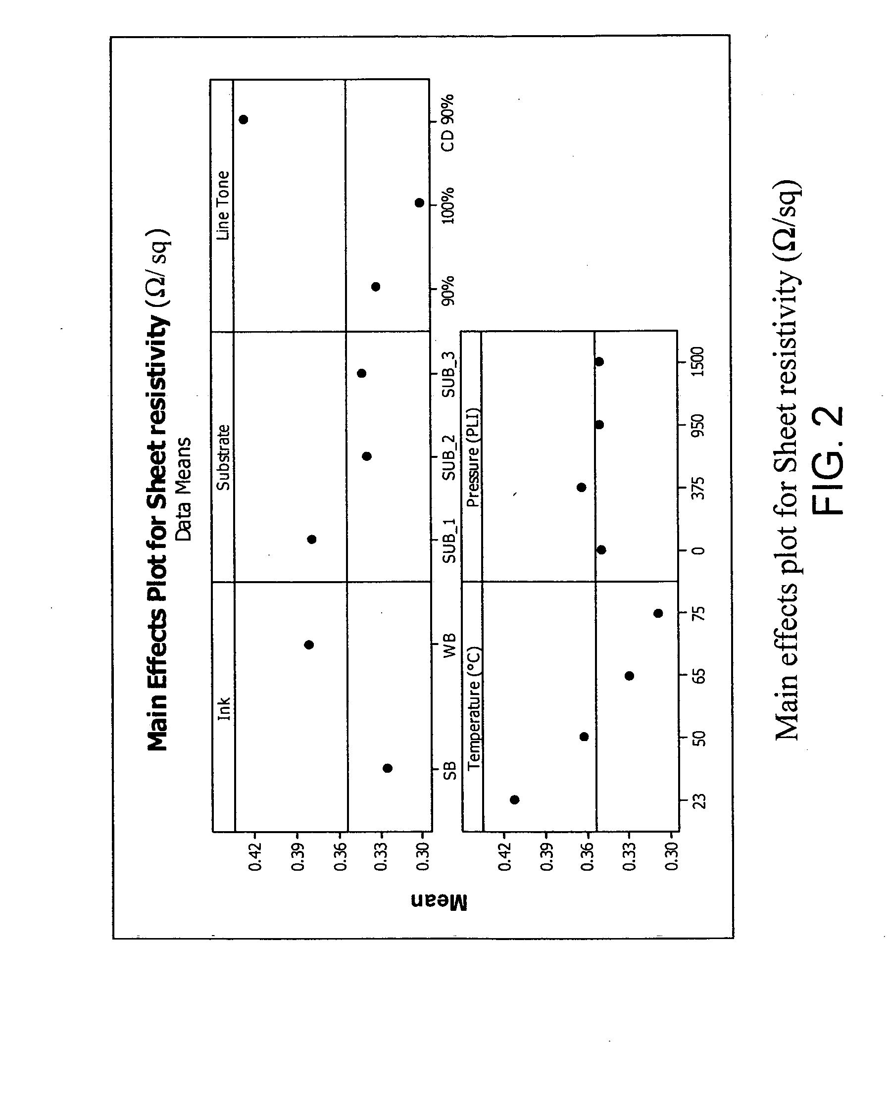
[0017]Conductive inks were printed using a Comco Commander narrow-web flexographic press. For this study, three packaging papers were selected. The first was a heat seal pouch paper (Sub1), the second was a beer bottle label paper (Sub2) and the third was a thermal transfer barcode paper (Sub3). Two ink systems were used in order to compare how different inks perform at different calendering conditions. Water-based, WB, and solvent-based, SB, silver-flake conductive inks were used. The printing design included lines at 4 different tones, 70, 80, 90 and 100%. A 90% tone trace was printed in both, machine and cross direction. Moreover, 50 mm×35 mm rectangles at 90 and 100% tones were included to enable sufficient area for measurements of printed ink film roughness. The Alien Technology UHF RFID tag “squiggle” (2nd generation) antenna design was also printed at 90 and 100% tone. To ensure sufficient drying, three dryers were used during printing, all set to 107° C. A 12 BCM (Bil...


PUM


Abstract

A method and system for improving the electrical conductivity of a conductive ink trace pattern provided on a substrate involves the printing of a conductive ink on a substrate to form a trace pattern thereon, fixing the trace pattern to the substrate and performing calendering on the substrate having the trace pattern fixed thereto.

Description

FIELD OF THE INVENTION[0001]The present invention is concerned with the provision of a conductive ink trace pattern on a substrate and, more particularly, to a method and system for improving the electrical conductivity of a conductive ink trace pattern provided on a substrate.BACKGROUND OF THE INVENTION[0002]Electrically conductive inks are being used more and more to form conductive circuits on a substrate. Flexible substrates having circuits formed thereon from electrically conductive ink have been used in many applications, such as automobile dashboards, appliance control panels, aircraft backlit panels, computers and in radio frequency identification (RFID) technology. Various types of printing processes have been used to print the electrically conductive ink on the substrate such as silk screen printing, ink jet printing, laser printing, rotogravure printing flexographic printing and lithographic printing. However, whatever method is used to print the electroconductive ink, th...

Claims


Application Information

Patent Timeline
IPC IPC(8): B41J2/01B41F31/00
CPCB41F23/00B41F31/00B41P2200/12B41P2200/20H05K2203/1105B41P2200/40H05K3/1283H05K2203/0143H05K2203/0278B41P2200/30
Inventor JOYCE, MARGARETFLEMING, PAUL D.PANDKAR, SUJAY PRABHAKAR
Owner WESTERN MICHIGAN UNIVERSITY
Why Eureka
Try Eureka