
Fixed-focus lens

a fixed-focus lens and lens technology, applied in the field of lenses, can solve the problems of increased projector cost and possible aberration of images projected thereby, and achieve the effects of reducing cost, good optical characteristics, and eliminating aberration

Active Publication Date: 2010-09-16
YOUNG OPTICS
View PDF16 Cites 8 Cited by
  • Summary
  • Abstract
  • Description
  • Claims
  • Application Information

AI Technical Summary

Benefits of technology

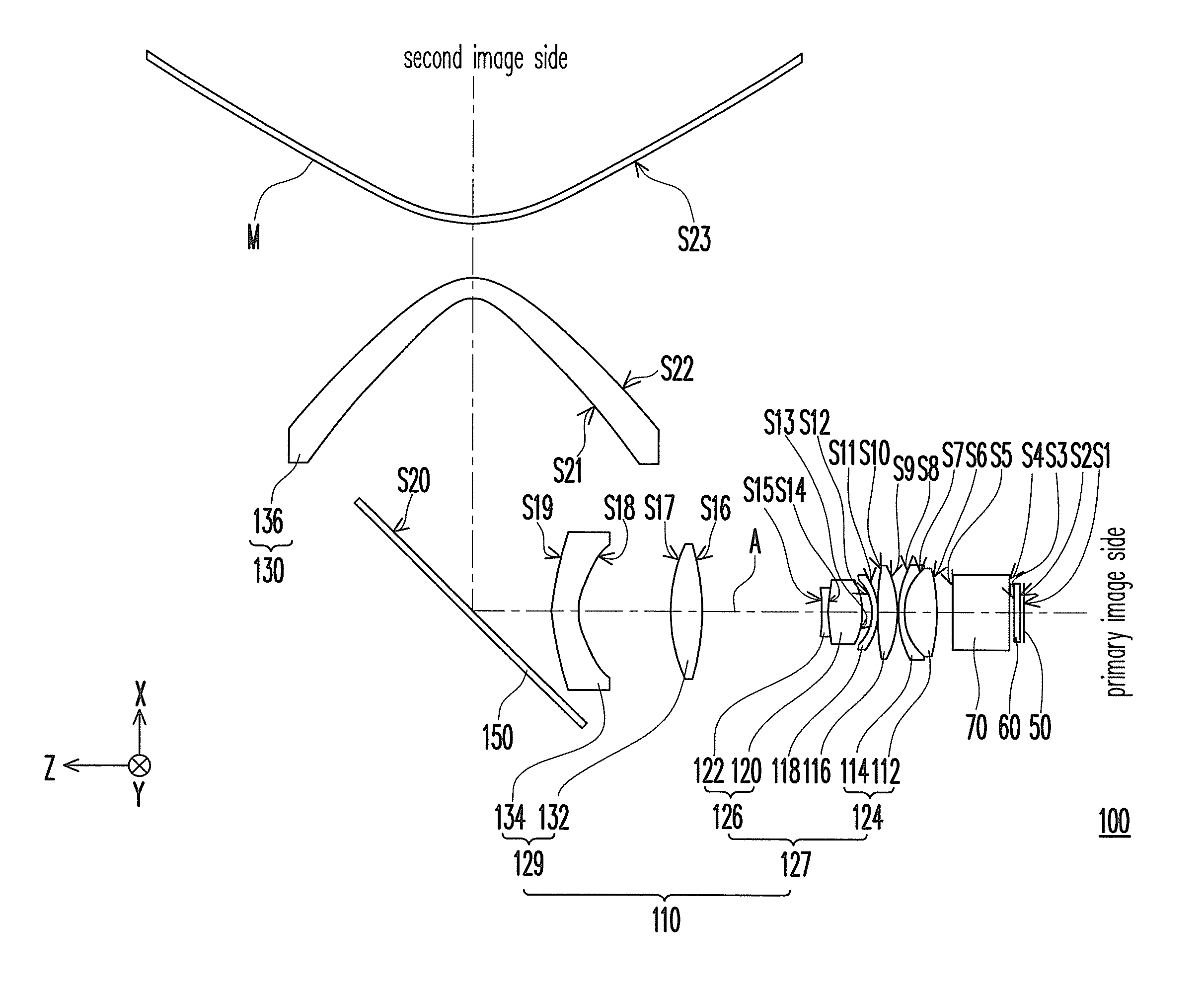
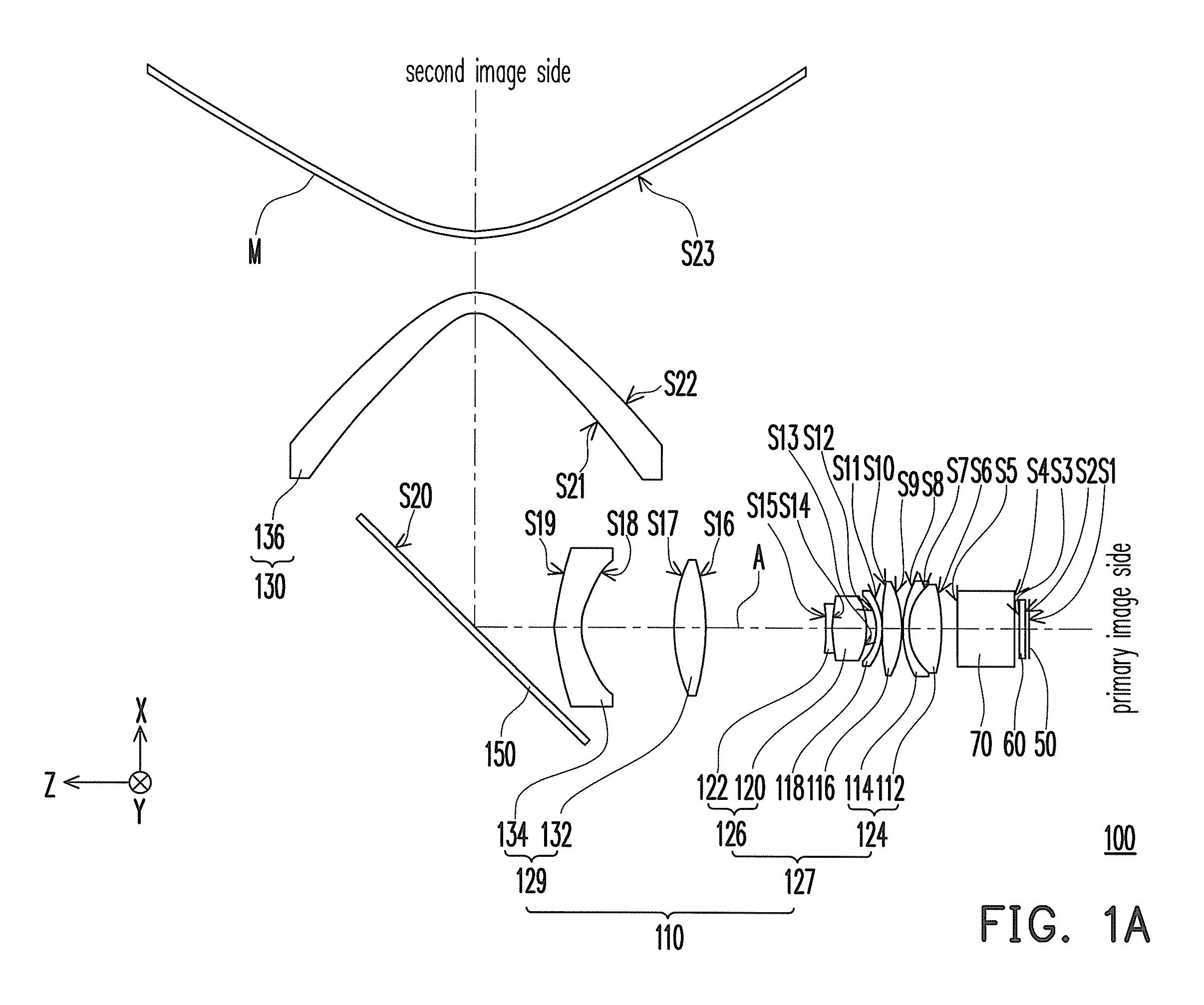
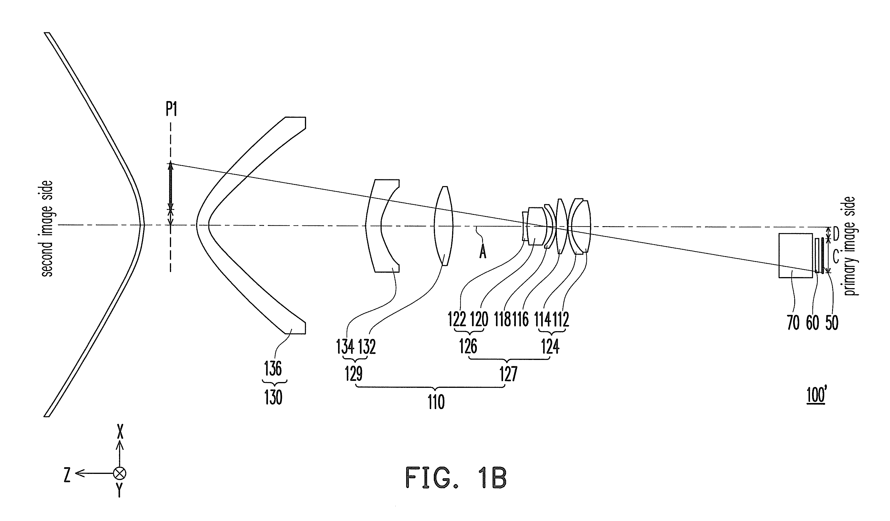
[0007]The invention provides a fixed-focus lens which has low cost and good optical characteristics. The above-described fixed-focus lens is capable of effectively eliminating aberration and reducing volume of a projection system using the same.
[0014]In view of the above, the embodiment or the embodiments of the invention may have at least one of the following advantages, by using the curved reflector with the first lens group and the second lens group, the fixed-focus lens in the embodiment of the invention is capable of eliminating aberration, and the fixed-focus lens has relatively wide field of view (FOV) through the configuration thereof. Furthermore, each of the three lenses, i.e. the first lens, the second lens, and the third lens, closest to the primary image side in the fixed-focus lens is a spherical lens, and the refractive powers of the first lens and the third lens are both positive. Accordingly, while less lenses and reflectors are used in the fixed-focus lens, it still has good optical characteristics. Therefore, the projection apparatus adopting the above-described fixed-focus lens is capable of effectively eliminating aberration, enhancing image quality, and reducing volume of the projection system thereof.

Problems solved by technology

However, the images projected thereby may have aberration, such as distortion, field curvature, and astigmatism.
However, it may enhance difficulty of manufacturing and fabricating the lens to increase the number of lenses used therein and to add the plurality of reflectors thereinto for reducing the overall length thereof while improving aberration, and cost of the projector is increased.

Method used


Image

  • Fixed-focus lens
  • Fixed-focus lens
  • Fixed-focus lens

Examples


Embodiment Construction

[0026]In the following detailed description of the preferred embodiments, reference is made to the accompanying drawings which form a part hereof, and in which are shown by way of illustration specific embodiments in which the invention may be practiced. In this regard, directional terminology, such as “top,”“bottom,”“front,”“back,” etc., is used with reference to the orientation of the Figure(s) being described. The components of the present invention can be positioned in a number of different orientations. As such, the directional terminology is used for purposes of illustration and is in no way limiting. On the other hand, the drawings are only schematic and the sizes of components may be exaggerated for clarity. It is to be understood that other embodiments may be utilized and structural changes may be made without departing from the scope of the present invention. Also, it is to be understood that the phraseology and terminology used herein are for the purpose of description an...


PUM


Abstract

A fixed-focus lens adapted to be disposed between a primary image side and a second image side is provided. The fixed-focus lens includes a second lens group, a first lens group, and a curved reflector arranged in sequence from the primary image side to the second image side. The second lens group includes a first lens, a second lens, and a third lens arranged in sequence from the primary image side to the second image side. The first lens and the third lens have positive refractive powers and each of the first lens, the second lens, and the third lens is a spherical lens.

Description

CROSS-REFERENCE TO RELATED APPLICATION[0001]This application claims the priority benefit of U.S. provisional application Ser. No. 61 / 202,556, filed on Mar. 12, 2009. This application also claims the priority benefit of Taiwan application serial no. 98117796, filed on May 27, 2009. The entirety of each of the above-mentioned patent applications is hereby incorporated by reference herein and made a part of this specification.BACKGROUND OF THE INVENTION[0002]1. Field of the Invention[0003]The invention generally relates to a lens, and more particularly, to a fixed-focus lens.[0004]2. Description of Related Art[0005]A fixed-focus lens is generally used in an optical system. The fixed-focus lens is widely applied therein, such as a monitoring camera, an automotive camera, a rear projection TV, a projector, etc. Along with development of optoelectronic technology, projectors having high quality have become more and more popular in recent years. In order to reduce the distance from the pro...

Claims


Application Information

Patent Timeline
IPC IPC(8): G02B17/08
CPCG02B13/06G02B17/0852G02B17/08G02B13/16
Inventor KANG, YI-HAOSU, YUAN-HUNG
Owner YOUNG OPTICS
Learn More