Imprint apparatus and method

a technology of imprinting apparatus and printing method, which is applied in the direction of coatings, pretreated surfaces, instruments, etc., can solve the problems of reducing dimensional accuracy and prolonging the transfer time of temperature control

Inactive Publication Date: 2010-09-16
CANON KK
View PDF2 Cites 24 Cited by
  • Summary
  • Abstract
  • Description
  • Claims
  • Application Information

AI Technical Summary

Benefits of technology

[0009]One of aspects of the present invention provides an imprint apparatus which includes an imprint head configured to hold a mold, and performs an imprint process including dispensing of a resin to a shot region on a substrate and pressing of the mold and the dispensed resin with each other, the apparatus comprising a controller configured to control an order of the imprint process for a plurality of selected shot regions on the substrate, and a first dispenser and a second dispenser configured to dispense the resin, wherein the first dispenser is arranged on a side of a first direction with respect to the imprint head, and the second dispenser is arranged on a side of a second direction opposite to the first direction with respect to the imprint head, the substrate is arranged so as to make rows of a layout of the plurality of shot regions parallel with the first direction and the second direction, the first dispenser dispenses the resin to shot regions belonging to a first group of the layout, and the second dispenser dispenses the resin to shot regions belonging to a second group of the layout, the first group existing on a side of the first direction, the second group existing on a side of the second direction, and a difference between number of shot regions belonging to an rth (r is a natural number) row of the first group and number of shot regions belonging to the rth row of the second group being not more than 1, and the controller is configured to control the order so as to satisfy a first condition that if the imprint process has ended for all selected shot regions of one row of the layout, the imprint process is executed for selected shot regions of a next row of the layout, a second condition that a plurality of shot regions belonging to a rth row selected from the first group undergo the imprint process sequentially in an rth row selected direction that is parallel to the first direction and the second direction, a third condition that a plurality of shot regions belonging to the rth row selected from the second group undergo the imprint process sequentially in the rth row selected direction, and a fourth condition that with respect to one row of the layout, the selected shot regions of the first group and the selected shot regions of the second group alternately undergo the imprint process as long as it is possible.

Problems solved by technology

In the heat-cycle method, temperature control prolongs the transfer time, and the dimensional accuracy lowers due to temperature changes.

Method used


Image

  • Imprint apparatus and method
  • Imprint apparatus and method
  • Imprint apparatus and method

Examples


first embodiment

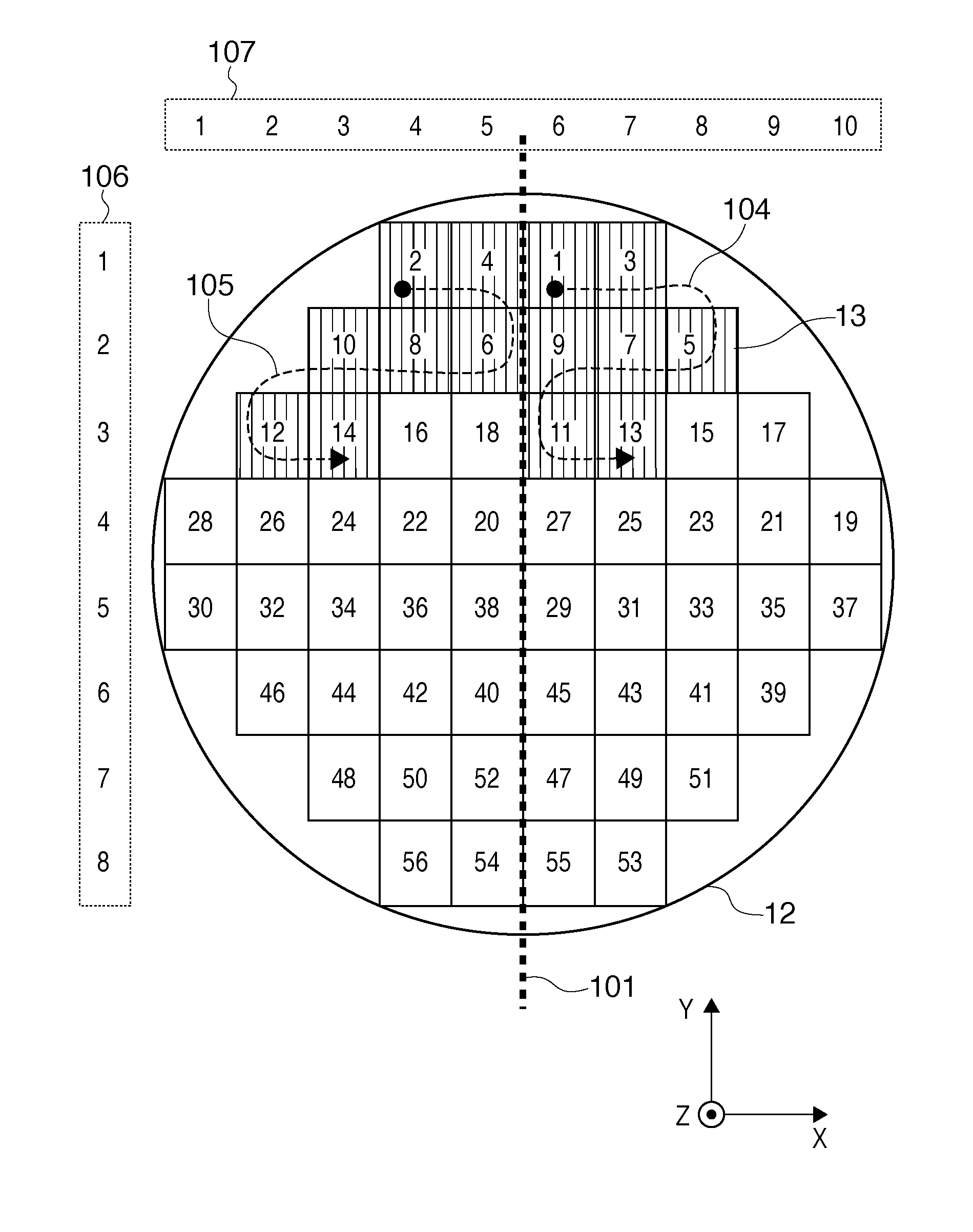
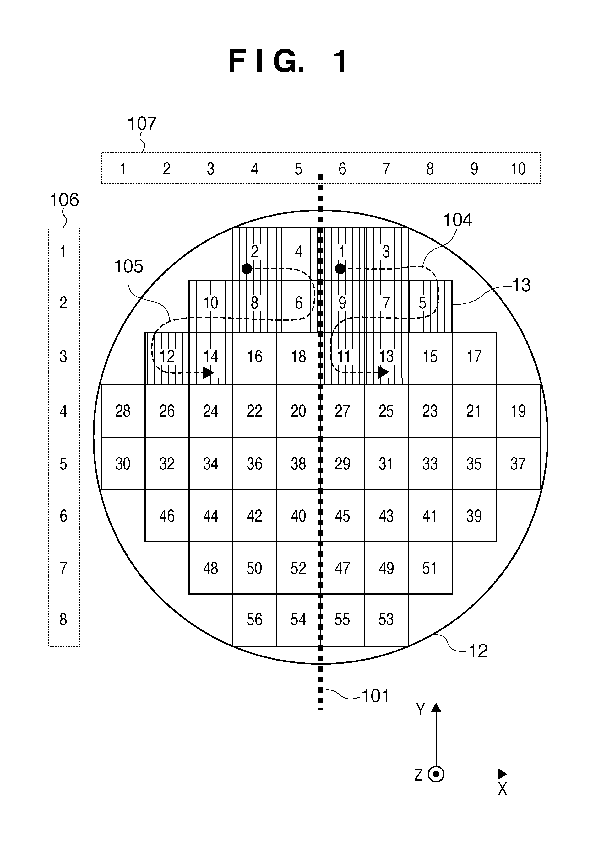
[0031]An imprint order according to the present invention will be exemplified with reference to FIG. 1. Referring to FIG. 1, each rectangle within the region on the substrate 12 represents a shot region. The number in each rectangle indicates the order of imprint. In the example of FIG. 1, the shot regions are laid out to be symmetrical with respect to the Y-axis.

[0032]The rows of the layout of the plurality of shot regions on the substrate 12 are defined to run in the X direction. The columns of the layout are defined to run in the Y direction. The shot regions of each row are divided into a first group on the +X direction (first direction) side and a second group on the −X direction (second direction) side. The division is done such that the difference between the number of shot regions belonging to the rth (r is a natural number) row of the first group and the number of shot regions belonging to the rth row of the second group is 1 or less. In the example of FIG. 1, the layout of...

second embodiment

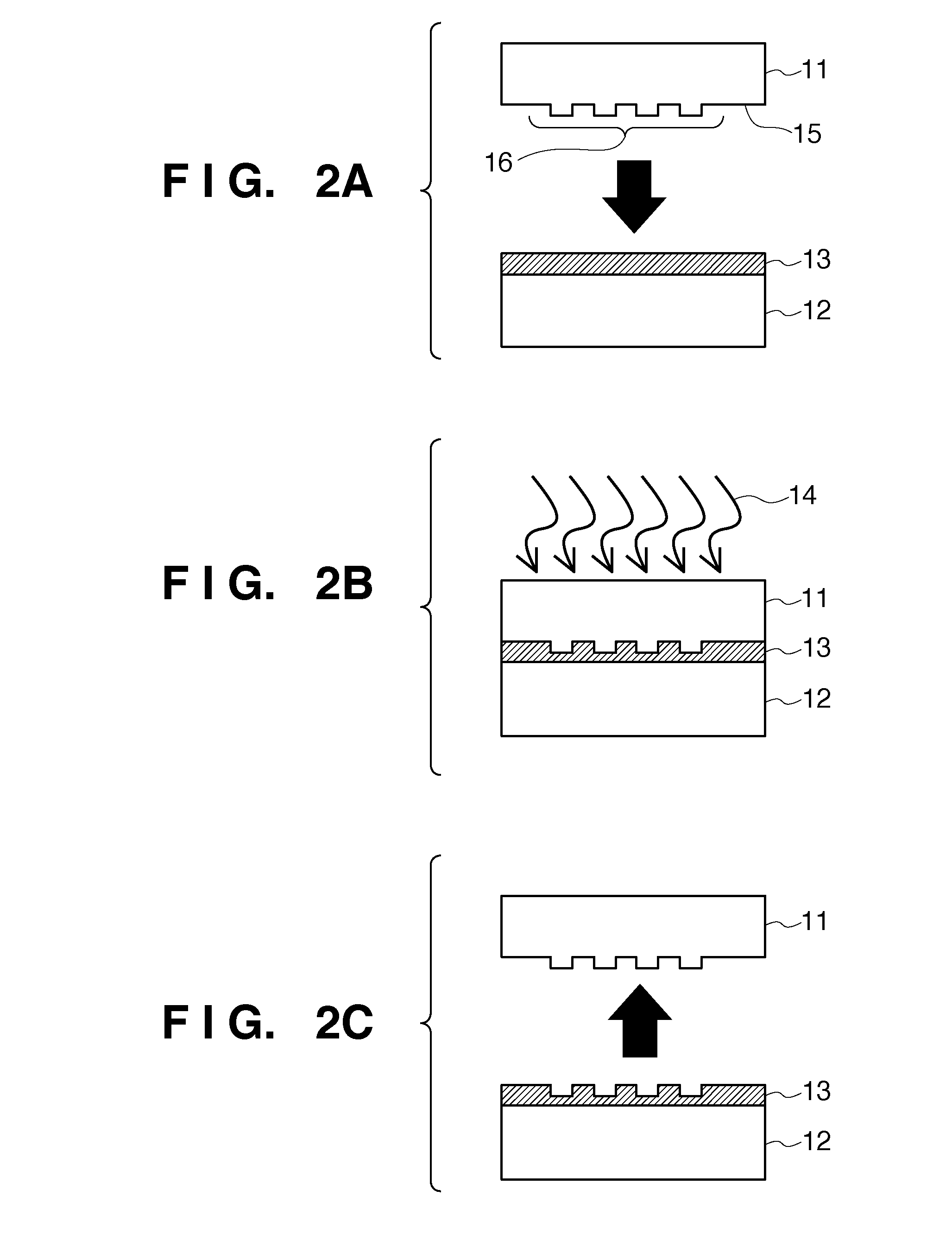
[0050]the present invention will be explained below. When a plurality of shot regions are arranged on a substrate in close vicinity to each other, it may be necessary to consider the resin at the boundary between the shot regions. When etching the underlying layer using the pattern formed by imprint, a gap in the resin between the shot regions causes etching of the layer at the gap portion. To the contrary, excess dispensing to a shot region may make the resin enter an adjacent shot yet to undergo imprint, and impede imprint for the adjacent shot.

[0051]In consideration of these problems, a useful layout is adopted in which a checkered pattern is formed by first shot regions where a first pattern should be formed and second shot regions where a second pattern having an area larger than the first pattern should be formed. The first and second patterns can be formed using a single mold 11. In this case, the first and second patterns can selectively be formed by changing the amount of t...


PUM

PropertyMeasurementUnit
glass transition temperatureaaaaaaaaaa
temperatureaaaaaaaaaa
fluidityaaaaaaaaaa

Abstract

An imprint apparatus which includes an imprint head configured to hold a mold, and performs an imprint process including dispensing of a resin to a shot region on a substrate and pressing of the mold and the dispensed resin with each other, comprises a controller configured to control an order of the imprint process for a plurality of selected shot regions on the substrate, and a first dispenser and a second dispenser configured to dispense the resin, wherein the first dispenser is arranged on a side of a first direction with respect to the imprint head, and the second dispenser is arranged on a side of a second direction opposite to the first direction with respect to the imprint head.

Description

BACKGROUND OF THE INVENTION[0001]1. Field of the Invention[0002]The present invention relates to an imprint apparatus and method.[0003]2. Description of the Related Art[0004]Nano-imprinting is a technique of enabling transfer of nanometer scale fine patterns and is well on its way to practical use as a nanolithography technique applicable to the mass production of magnetic storage media or semiconductor devices. In nano-imprinting, a fine pattern is formed on a substrate such as a silicon wafer or a glass plate using, as a mask, a mold with a fine pattern formed by an apparatus such as an electron-beam exposure apparatus. The fine pattern is formed by dispensing a nanoimprint resin to the substrate and curing the resin on the substrate, which is being pressed by the mold.[0005]Nano-imprint techniques currently in practical use are the heat-cycle method and the photocuring method. In the heat-cycle method, a thermoplastic nanoimprint resin on a substrate is heated to the glass transi...

Claims


Application Information

Patent Timeline
Patent Type & Authority Applications(United States)
IPC IPC(8): B05D3/12
CPCB29C35/0888B29C59/022B29C2035/0827G03F7/0002B82Y10/00B82Y40/00B29C2059/023G03F7/161
Inventor AOKI, AKIOINADA, HIROSHIKOHDA, TOHRUINA, HIDEKISATO, HIROSHI
Owner CANON KK
Why Eureka
Try Eureka