System for inertial particles separation

a technology of inertial particles and filtering system, which is applied in the direction of filtration separation, climate sustainability, efficient propulsion technology, etc., can solve the problems of increasing fuel consumption, increasing operational and maintenance costs, and affecting the performance of the engine, so as to achieve the effect of longer operation life and better performan

Inactive Publication Date: 2010-09-23
KING FAHD UNIVERSITY OF PETROLEUM AND MINERALS
View PDF15 Cites 15 Cited by
  • Summary
  • Abstract
  • Description
  • Claims
  • Application Information

AI Technical Summary

Benefits of technology

[0028]The curvatures of the first wall and the splitter member are selectively and controllably variable. Since the helicopter may be required to operate under different operational and environmental conditions, the specific geometric design of the airfoil profiles that defines the internal flow paths of the system may be redefined in real time. This is accomplished by employing surface morphing and flow suction techniques that allow the system to alter the sand particle trajectories, as well as flow streamlines to prevent particles from entering the aircraft engine inlet (joined to the outlet of the air flow), resulting in better performance and longer operational life of the engine.

Problems solved by technology

Any such equipment operating under such conditions for long periods is vulnerable to internal system and / or engine damage.
Internal engine damage can range from simple erosion in the engine blades to a completely inoperative engine with as little as half a pound of sand.
Even without mechanical damage, degradation of the performance and efficiency of the aircraft's engine leads to increases in fuel consumption, and in operational and maintenance costs.
No form of mechanical or electrical power is used as a part of such systems, which keeps the engine performance unaffected.

Method used


Image

  • System for inertial particles separation
  • System for inertial particles separation
  • System for inertial particles separation

Examples


Embodiment Construction

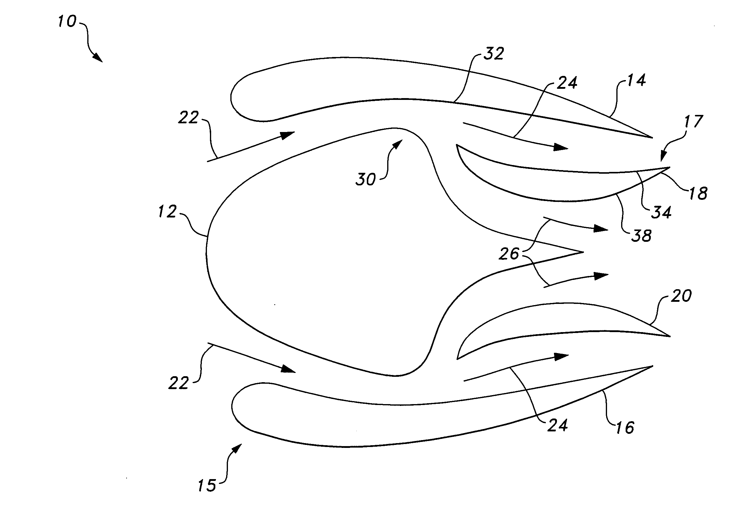
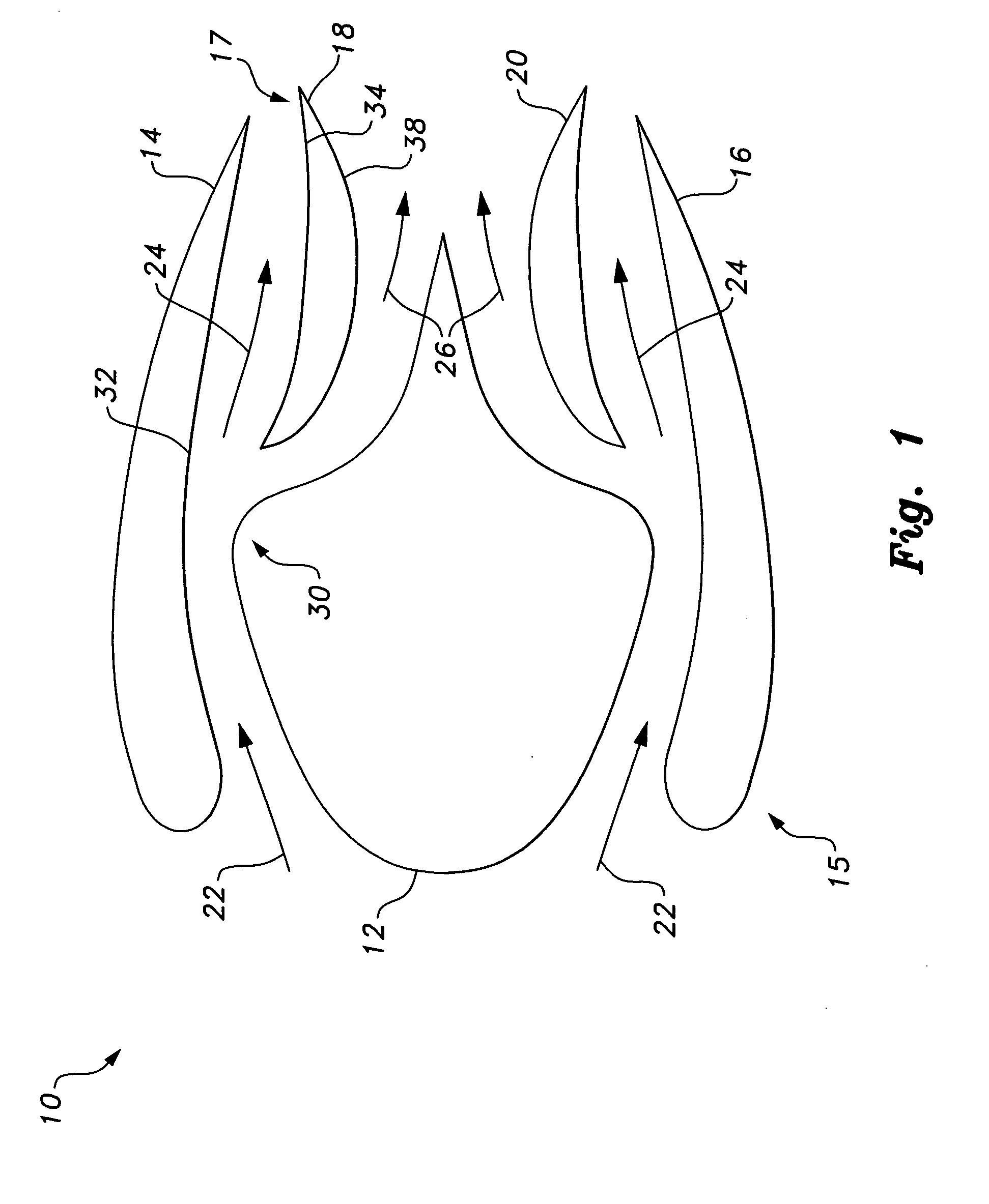
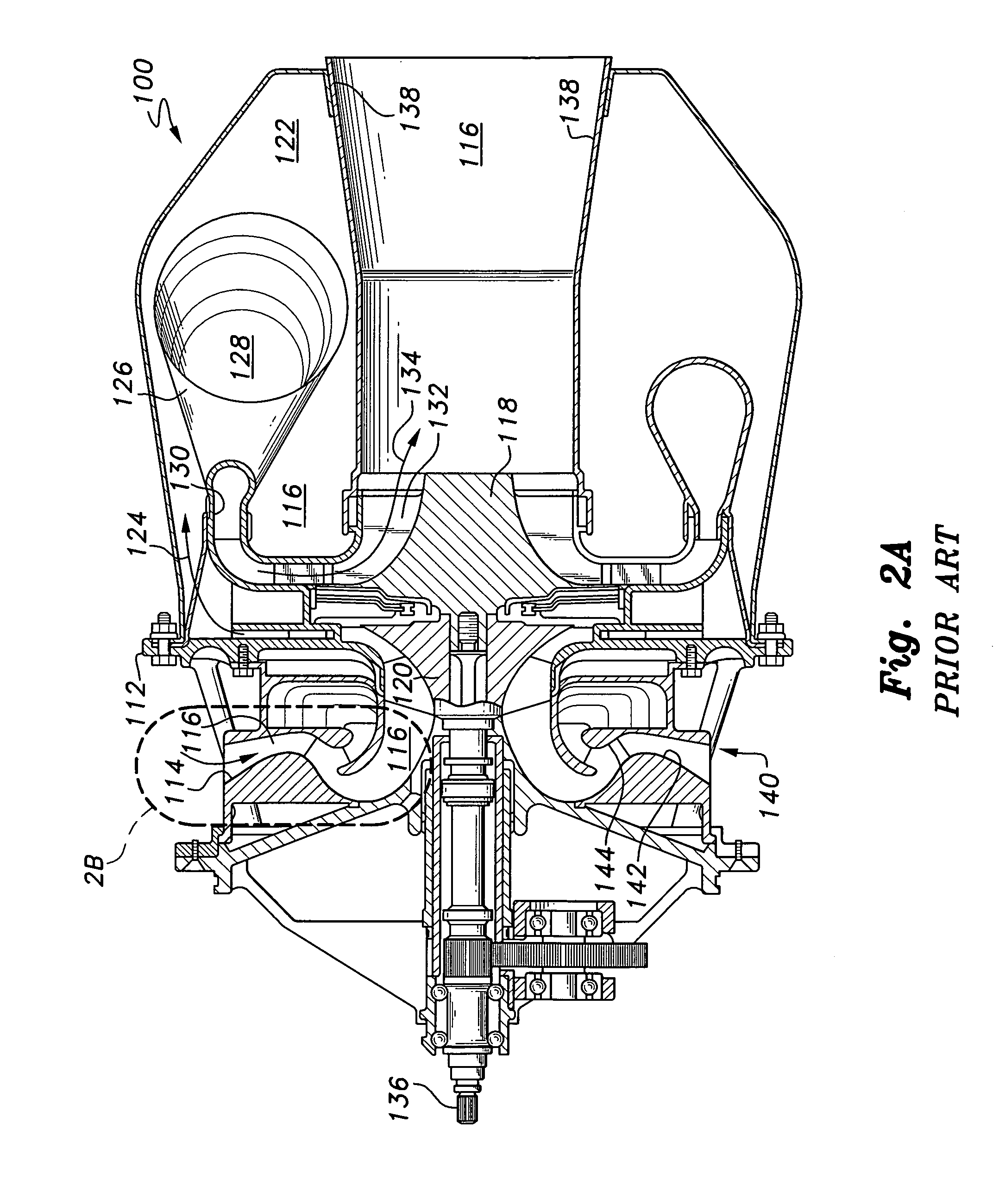
[0035]FIG. 1 diagrammatically shows a system for inertial particle separation, designated generally as 10 in the drawing, illustrated for an axial air flow turbine engine of the like. The system 10 removes particulate matter, such as sand, from an air stream, such as that drawn into a helicopter turbine engine. The system 10 includes first and second walls 32, coaxially and radially spaced apart, and positioned within an outer housing of the turbine engine or the like. As shown, first wall 32 is formed as an internal face of airfoil member 14, and second wall 30 is preferably defined by the outer wall of a hub 12. The following discussion will be directed towards only the upper airfoil member 14 in relation to central hub 12, in a manner similar to the focus of FIG. 2B. As in FIG. 2A, there are a pair of symmetric air flow channels, with the lower air flow being defined by a second, lower symmetric airfoil member 16, identical to upper airfoil member 14. Preferably, the cross-sectio...


PUM

PropertyMeasurementUnit
curvatureaaaaaaaaaa
temperatureaaaaaaaaaa
pressureaaaaaaaaaa

Abstract

The system for inertial particle separation removes particulate matter, such as sand, from an air stream, such as that drawn into a turbine engine. The system includes first and second walls spaced apart and positioned within a housing of the turbine engine. The first wall is in the form of an airfoil with variable geometry. An annular air flow path is defined between the first and second walls. The air flow path leads inwardly from an ambient inlet and turns to an outlet. A splitter member is positioned between the first and second walls. A scavenge flow path is defined between the splitter member and the first wall. An inlet thereof is in communication with the ambient inlet, and a filtered flow path is defined between the splitter member and the second wall. The splitter member is also in the form of an airfoil having a variable geometry.

Description

BACKGROUND OF THE INVENTION[0001]1. Field of the Invention[0002]The present invention relates to filtering systems, and particularly to a system for inertial particle separation that is provided for removing particulate matter, such as sand, from an air stream, such as that drawn into a helicopter turbine engine.[0003]2. Description of the Related Art[0004]In a typical desert environment, the ambient air is often filled with sand and dust particles. The operational performance and life of any mechanical equipment, such as air ingestion systems of turbine engines, air-conditioning systems, air-breathing engines or the like, which are designed to operate in such a harsh environment, is greatly influenced by the presence of sand and dust. Any such equipment operating under such conditions for long periods is vulnerable to internal system and / or engine damage.[0005]For example, the operational life of a helicopter's engine operating in sandy environments can be as short as fifty hours. ...

Claims


Application Information

Patent Timeline
Patent Type & Authority Applications(United States)
IPC IPC(8): F02C7/052B01D45/04
CPCB01D45/04F02C7/042Y02T50/675F04D29/701F05D2260/607F02C7/052Y02T50/60
Inventor SAEED, FAROOQAL-GARNI, AHMED
Owner KING FAHD UNIVERSITY OF PETROLEUM AND MINERALS
Why Eureka
Try Eureka