Hydrogen gas storing device

a technology of hydrogen gas and storage device, which is applied in the direction of chemistry apparatus and processes, mechanical apparatus, lighting and heating apparatus, etc., can solve the problems of single heat exchanger not meeting the performance requirements of electric vehicles having fuel cells, inability to secure, and inability to install heat exchangers, etc., to achieve the effect of increasing strength and preventing damag

Inactive Publication Date: 2010-09-23
TOYOTA IND CORP +1
View PDF9 Cites 22 Cited by
  • Summary
  • Abstract
  • Description
  • Claims
  • Application Information

AI Technical Summary

Benefits of technology

[0026]In this case, the curved portions reinforce the fins so that the fins have an increased strength against forces in a direction opposite to the direction of the recess. Therefore, even if the hydrogen absorbing metal filling the accommodation chambers is thermally expanded when absorbing hydrogen, and an outward force acts on the fins, the fins are prevented from being damaged.

Problems solved by technology

However, when the heat exchanger incorporating metal hydride disclosed in Patent Document 1 is installed on, for example, an electric vehicle having a fuel cell, a space having desired shape and size cannot be secured at a planned installation position (for example, between the axle of the rear wheels and the rear seats), and, in some cases, the heat exchanger cannot be installed.
In this case, if the size of the heat exchanger is reduced, the single heat exchanger cannot provide performance required for an electric vehicle having a fuel cell.
Therefore, the heat exchanger incorporating metal hydride disclosed in Patent Document 1 has a disadvantage in that it can be installed in only limited locations.
However, in this case, each of the heat exchangers needs to be fixed to the vehicle separately, which makes the installation of the heat exchangers troublesome.

Method used


Image

  • Hydrogen gas storing device
  • Hydrogen gas storing device
  • Hydrogen gas storing device

Examples


Embodiment Construction

[0034]One embodiment of the present invention will now be described with reference to FIGS. 1 to 4.

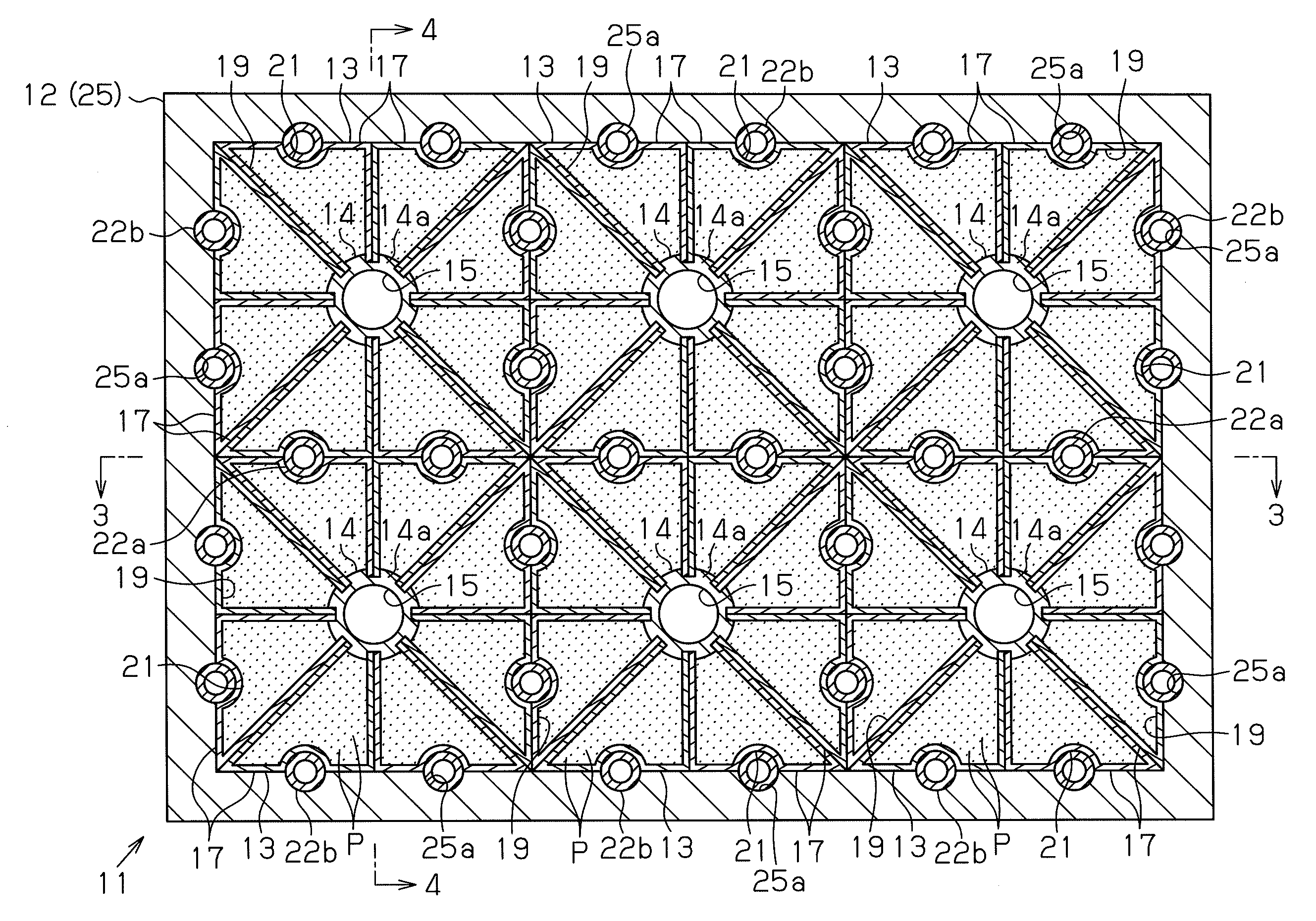
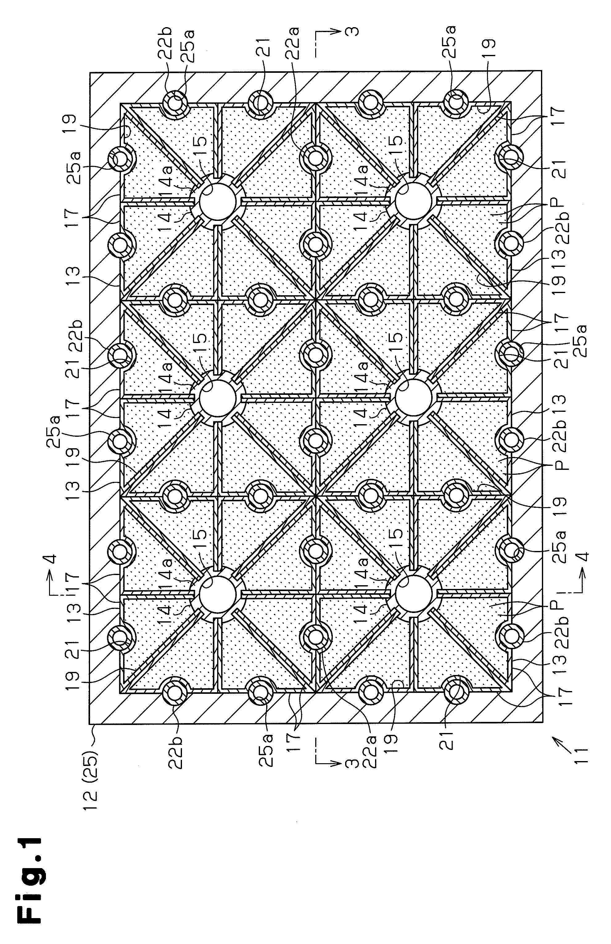
[0035]As shown in FIG. 1, a hydrogen gas storing device 11 includes a substantially rectangular box-shaped housing 12 (which is, for example, made of aluminum). A plurality of (six in the present embodiment) of MH tank modules 13, serving as tank modules, are arranged in the housing 12. Specifically, the MH tank modules 13 are arranged adjacent to each other to form a substantially quadrangular prism shape. In the housing 12, the MH tank modules 13 are stacked to form multiple stages. The housing 12 has such a strength that it sufficiently withstands an inner pressure of a predetermined value (for example, 10 MPa) when the MH tank modules 13 are fully filled with hydrogen.

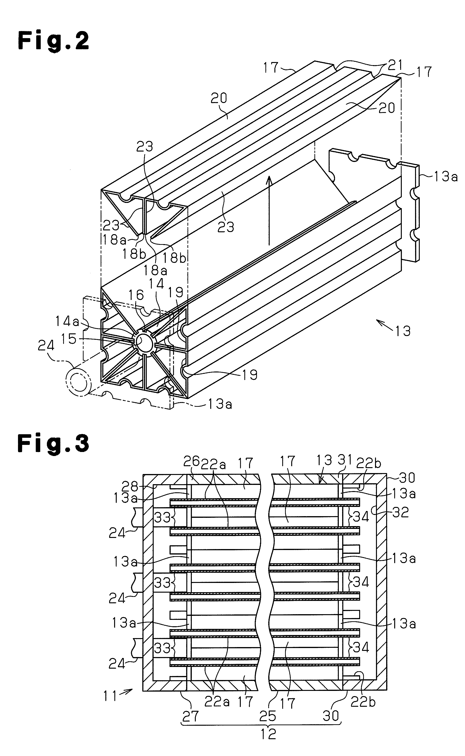
[0036]As shown in FIG. 2, each MH tank module 13 has a porous member 14, which serves as a cylindrical member formed of a porous material, at the center. The cross section of the MH tank module 13 taken along a direct...


PUM


Abstract

A plurality of MH tank modules (13) each include a cylindrical porous member (14). The porous member (14) is formed as a hydrogen flow path (15) through which hydrogen can flow and has straight grooves formed on the outer circumferential surface. A plurality of fins (17) are attached to the porous member (14). A first edge and a second edge of each fin (17) are fitted in different grooves. The fins (17) define a plurality of accommodation chambers (19) for accommodating MH powder P. The MH tank modules (13) are accommodated in the housing while being arranged adjacent to each other to form a predetermined shape. Heat medium pipes (22a, 22b) are arranged in the housing (12) so as to contact the fins (17) and correspond to the accommodation chambers (19). Heat medium flows through the heat medium pipes (22a, 2b). Therefore, it is possible to provide a hydrogen gas storing device that easily increases the number of places to be installed in and facilitates the installment.

Description

TECHNICAL FIELD[0001]The present invention relates to a hydrogen gas storing device.BACKGROUND ART[0002]As a hydrogen storage tank, there is known a technique in which powdered hydrogen absorbing metal (hereinafter, referred to as MH) is accommodated in a tank, and MH absorbs and stores hydrogen, and releases hydrogen to be utilized.[0003]MH has a property of generating heat when storing hydrogen and a property of absorbing heat when releasing hydrogen. Each time MH stores and releases hydrogen, the MH generates or absorbs heat. Therefore, a hydrogen storage tank using MH may be provided with a function of a heat exchanger that heats and cools the MH.[0004]As one example of a hydrogen storage tank that accommodates MH and has a function as an heat exchanger, a heat exchanger incorporating metal hydride has been proposed, in which an inner space between a sealed cylinder and a hydrogen pipe therein is divided into a plurality of small chambers with partitions, and each small chamber ...

Claims


Application Information

Patent Timeline
Patent Type & Authority Applications(United States)
IPC IPC(8): F28F1/30
CPCC01B3/0005C01B3/0026Y02E60/327F17C11/005Y02E60/321C01B3/0031Y02P90/45Y02E60/32
Inventor TOH, KEIJIMORI, DAIGOROHIROSE, KATSUHIKOHARAIKAWA, NORIHIKO
Owner TOYOTA IND CORP
Why Eureka
Try Eureka