
Multiplexed Detection Schemes for a Droplet Actuator

a detection scheme and actuator technology, applied in the direction of fluid pressure measurement, liquid/fluent solid measurement, peptides, etc., can solve the problems of interfering with the droplet operation of subsequent droplets, interfering with the detection of subsequent signals, etc., to facilitate the use of the droplet actuator, facilitate the sensing of a property or a signal, and improve the throughput of droplet operations

Inactive Publication Date: 2010-09-23
ADVANCED LIQUID LOGIC
View PDF101 Cites 115 Cited by
  • Summary
  • Abstract
  • Description
  • Claims
  • Application Information

AI Technical Summary

Benefits of technology

[0030]When a droplet is described as being “on” or “loaded on” a droplet actuator, it should be understood that the droplet is arranged on the droplet actuator in a manner which facilitates using the droplet actuator to conduct one or more droplet operations on the droplet, the droplet is arranged on the droplet actuator in a manner which facilitates sensing of a property of or a signal from the droplet, and / or the droplet has been subjected to a droplet operation on the droplet actuator.DESCRIPTION OF THE INVENTION
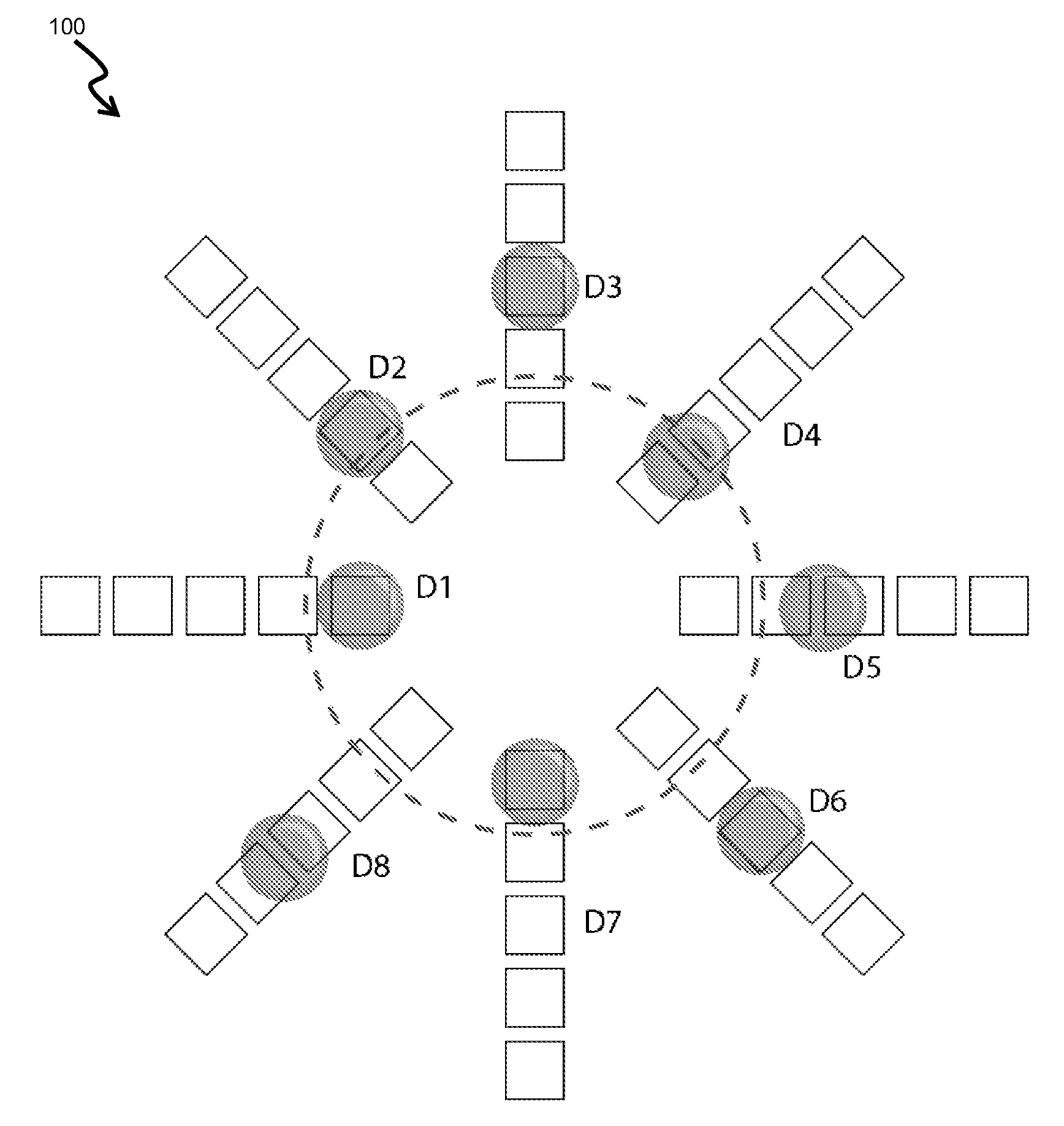
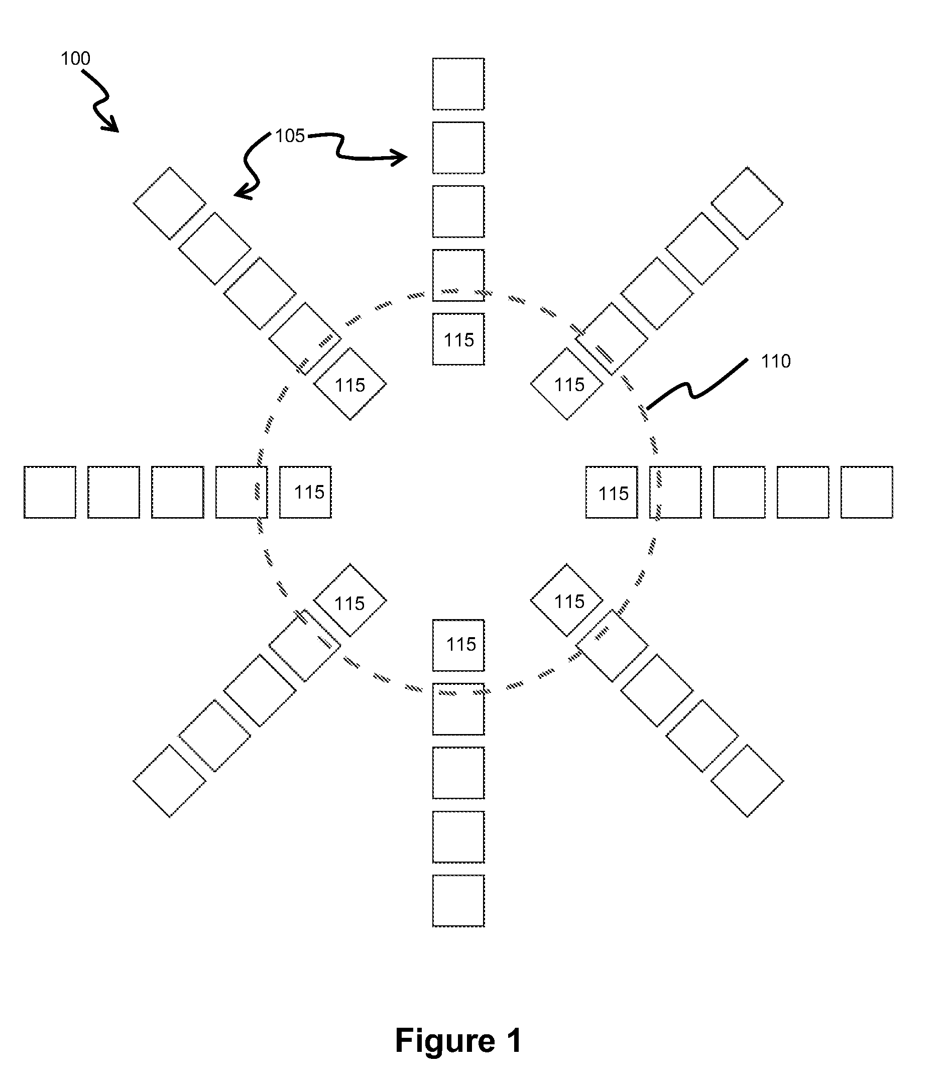
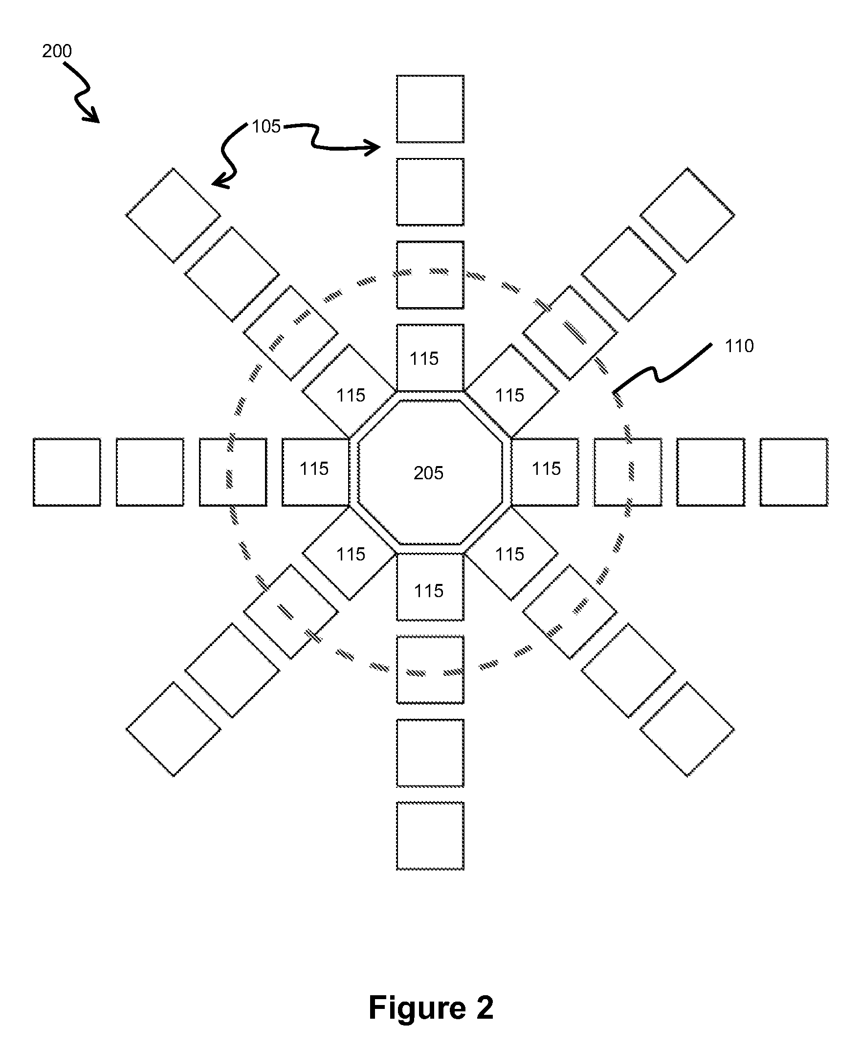
[0031]The invention provides droplet actuators configured to improve the throughput of droplet operations in a detection spot of the droplet actuator and / or to reduce carryover problems, such as carry over problems related to biochemical, chemical, particulate, bead, and / or optical carryover at a detection spot. A detection spot is a location on a droplet microactuator where a droplet is positioned during detection of a property of a droplet. A detection spot may be associated with one or more electrodes configured for conducting droplet operations; however, droplets may be placed on detection spots using a variety of other mechanisms as well, such as hydrophilic or hydrophobic surfaces and / or droplet movement controlled by movement of filler fluid in the droplet actuator. The detection spot is typically in proximity to a sensor apparatus, such as a photomultiplier tube (PMT) or a photon counting PMT or a photodiode or an electrochemical sensor. The invention provides several alternative approaches to solving the throughput issues associated with the detection spot. In one approach, illustrated by certain examples described in Section 6.1, the droplet actuator includes multiple detection spots within the diameter of exposure to the sensor, which we refer to as the “detection window” of the sensor. In this manner, multiple droplets can undergo detection without requiring all droplets to pass over or reside on the same detection spot. In another approach, illustrated by certain examples described in Section 6.2, the conformations or positions of multiple droplets are modulated in the presence of the detector to create a signal, which can be demodulated to quantify the signal of each independent droplet.

Problems solved by technology

Carryover of substances, such as compounds or beads, as well as carryover of signals, could be increased on a droplet microactuator when a single detection spot is used multiple times. Carryover can result in deposition of materials on a surface which interferes with droplet operations of subsequent droplets.
Deposition of materials on a surface can also result in background signal, which interferes with detection of signal from subsequent droplets.
Further, where the droplet actuator is made using fluorescent or phosphorescent substrate, such as the FR-4 material used in a PCB, the fluorescence or phosphorescence in the region of a detector can be enhanced by photons emitted from droplets, thereby interfering with detection of subsequent droplets.

Method used


Image

  • Multiplexed Detection Schemes for a Droplet Actuator
  • Multiplexed Detection Schemes for a Droplet Actuator
  • Multiplexed Detection Schemes for a Droplet Actuator

Examples


Embodiment Construction

[0031]The invention provides droplet actuators configured to improve the throughput of droplet operations in a detection spot of the droplet actuator and / or to reduce carryover problems, such as carry over problems related to biochemical, chemical, particulate, bead, and / or optical carryover at a detection spot. A detection spot is a location on a droplet microactuator where a droplet is positioned during detection of a property of a droplet. A detection spot may be associated with one or more electrodes configured for conducting droplet operations; however, droplets may be placed on detection spots using a variety of other mechanisms as well, such as hydrophilic or hydrophobic surfaces and / or droplet movement controlled by movement of filler fluid in the droplet actuator. The detection spot is typically in proximity to a sensor apparatus, such as a photomultiplier tube (PMT) or a photon counting PMT or a photodiode or an electrochemical sensor. The invention provides several altern...


PUM

PropertyMeasurementUnit
Shapeaaaaaaaaaa
Frequencyaaaaaaaaaa

Abstract

A droplet actualor having electrodes configured for ejecting droplet operations transporting droplets on a surface, and a sensor arranged in proximity to one or more of the electrodes establishing a detection window on the surface for detection of one or more properties of one or more droplets on the surface, wherein the electrodes establish at least two pathways for transport of droplets into the detection window. Also provided is, A method of detecting a property of a target droplet, including using droplet operations to modulate signals from a droplet set comprising the target droplet, detecting the modulated signals of the droplet set, demodulating the modulated signals to identify the signal produced by one or more individual droplets of the set Related methods and alternative embodiments are also provided.

Description

RELATED PATENT APPLICATIONS[0001]This application claims priority to U.S. Patent Application No. 60 / 980,487, entitled “Multiplexed detection schemes for a droplet actuator,” filed on Oct. 17, 2007, the entire disclosure of which is incorporated herein by reference.GOVERNMENT INTEREST[0002]This invention was made with government support under DK066956-02 and GM072155-02 awarded by the National Institutes of Health of the United States. The United States Government has certain rights in the invention.BACKGROUND OF THE INVENTION[0003]Carryover of substances, such as compounds or beads, as well as carryover of signals, could be increased on a droplet microactuator when a single detection spot is used multiple times. Carryover can result in deposition of materials on a surface which interferes with droplet operations of subsequent droplets. Deposition of materials on a surface can also result in background signal, which interferes with detection of signal from subsequent droplets. Furthe...

Claims


Application Information

Patent Timeline
IPC IPC(8): G01N35/10G01N27/26
CPCB01L3/502761B01L2400/0448B01L2200/0673B01L2300/0654B01L2300/0816B01L2300/0819B01L2300/0861B01L2300/0864B01L2300/0867B01L2300/087B01L2300/088B01L2300/089B01L2400/0424B01L2400/0427B01L3/502792
Inventor SRINIVASAN, VIJAYPAMULA, VAMSEE K.SISTA, RAMAKRISHNAPOLLACK, MICHAEL G.
Owner ADVANCED LIQUID LOGIC
Learn More