Liquid treatment apparatus and methods

a technology of liquid treatment apparatus and liquid treatment chamber, which is applied in the direction of vortex flow apparatus, separation process, filtration separation, etc., can solve the problems of increasing the vacuum within the chamber and the generation of more vapor, and achieves the effect of increasing vacuum, reducing the size of the bubble, and increasing shear

Inactive Publication Date: 2010-09-23
FLUID QUIP INC
View PDF87 Cites 9 Cited by
  • Summary
  • Abstract
  • Description
  • Claims
  • Application Information

AI Technical Summary

Benefits of technology

[0012]Alternatively, the tangentially directed inlet port in the cyclonettes of the '708 patent may be employed to inject a second stream of liquid into the cyclonette along its inside wall in a spiral flow path. Vapor within the cyclonette will tend to be dragged axially toward the discharge end by the linear jet and in a spiral path by the second liquid. When the two high-velocity liquid streams approach one another, the shear created due to the differences in velocity will tend to create a turbulent mixing zone that will disrupt the vapor film between the two liquids and generate bubbles. Increasing the fluid velocities will increase shear and reduce the size of the bubbles. It will also result in increased vacuum within the chamber and the generation of more vapor.
[0013]With this design cavitation initiates at very low inlet fluid pressure—on the order of 10 psi or less, with water at 30° C. and atmospheric pressure discharge. Also, the high shear generated helps reduce bubble size, which in turn, increases bubble surface to volume ratio and improves chemical reaction rates. As long as the velocity head of the fluid exiting the chamber exceeds the static pressure in the discharge zone, a vacuum will be generated within the chamber. Once pressure within the chamber drops to the vapor pressure of the liquid, vapor fills the cavity and cavitation occurs. Thus, the amount of vapor entrained is almost independent of pressure in the discharge zone.
[0014]As a modification of this embodiment, the main inlet jet may pass through a vortex finder of conventional design, except that, in addition to the flow being directed into the cyclonette from the vortex finder (instead of out of the cyclonette through the vortex finder), the vortex finder is modified to impart a spin to the incoming jet in a direction opposite to the direction of the tangential inlet flow. The result is that the collision of the two streams flowing in opposite directions creates a shear on the vapor trapped between the two streams that tears the vapor film into tiny bubbles, leading to increased cavitation efficiency.

Problems solved by technology

When the two high-velocity liquid streams approach one another, the shear created due to the differences in velocity will tend to create a turbulent mixing zone that will disrupt the vapor film between the two liquids and generate bubbles.
It will also result in increased vacuum within the chamber and the generation of more vapor.

Method used


Image

  • Liquid treatment apparatus and methods
  • Liquid treatment apparatus and methods
  • Liquid treatment apparatus and methods

Examples


Embodiment Construction

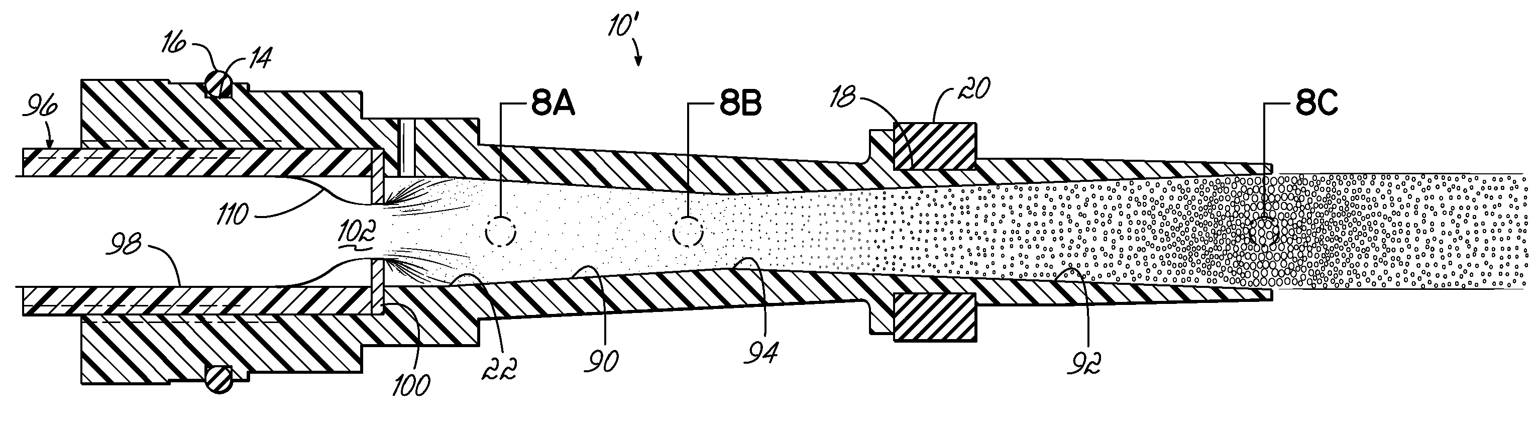
[0030]Turning initially to FIG. 6 of the drawings, a more or less conventional cyclonette 10 is shown with a vortex finder 12 installed in the left hand end of the cyclonette as it appears in FIG. 6 of the drawings. For a purpose to be presently described, the left-hand end of the cyclonette may be provided with an annular groove 14 into which an O-ring 16 may be seated. To the right of the O-ring 16, as seen in FIG. 6 of the drawings, a second annular groove 18 may be formed to receive a second O-ring 20 of more or less rectangular cross-sectional configuration. Interiorly of the cyclonette 10, a flow path is provided comprising a throat portion 22, an inwardly tapering flow channel 24, and a terminal flow channel 26 of narrower constant diameter. At its left-hand end, as seen in FIG. 6, the cyclonette 10 may be provided with an internally threaded socket 28 receiving the complementary external threads 30 of the vortex finder 12. The vortex finder has a uniformly inwardly tapering ...


PUM

PropertyMeasurementUnit
lengthaaaaaaaaaa
pressureaaaaaaaaaa
diameteraaaaaaaaaa

Abstract

Apparatus and methods for treatment of liquids by generating hydroxyl radicals through the dissolution of water molecules by hydraulic cavitation.

Description

CROSS-REFERENCE TO RELATED APPLICATION[0001]This application is a continuation of U.S. patent application Ser. No. 11 / 553,791, entitled “Liquid Treatment Apparatus and Methods,” filed Oct. 27, 2006 (pending), the contents of which are incorporated herein by referenceFIELD OF THE INVENTION[0002]The present invention relates to apparatus and methods for effecting the dissolution of water into hydroxyl radicals for the treatment of liquids.BACKGROUND OF THE INVENTION[0003]Centrifugal separation of solids carried in a liquid-solid suspension by hydrocyclonic technology involves tangentially feeding the suspension into an open-ended, circular cylinder having an inwardly tapering inner diameter and extracting from its apex heavier solids, while collecting finer solids from its larger opposite end. Individual hydrocyclone cylinders may be relatively small—on the order of about four inches in length and with an inner diameter tapering from about a half inch to about a tenth of an inch—and a...

Claims


Application Information

Patent Timeline
Patent Type & Authority Applications(United States)
IPC IPC(8): C02F1/34C02F1/72
CPCB01J19/008B01J2219/00024C02F1/34B04C5/13B04C5/28B01J2219/00038
Inventor SPRAGUE, ALLISON
Owner FLUID QUIP INC
Why Eureka
Try Eureka