
Method for Determining the Phases in a Multi-Phase Electrical System and Device for The Implementation Thereof

Active Publication Date: 2010-09-23
ABB (SCHWEIZ) AG
View PDF3 Cites 18 Cited by
  • Summary
  • Abstract
  • Description
  • Claims
  • Application Information

AI Technical Summary

Benefits of technology

[0009]One embodiment of the invention has the object of eliminating the need for a GPS signal to identify the phase of the multi-phase system.
[0010]An object of a further embodiment of the invention is to provide a device and a method that allow detection and identification of the phases in a multi-phase electrical system, wherein the phase detecting device does not require to be connected galvanically, in order to make operations faster and safer, avoiding the need to restore the insulation of cables after measurement.
[0021]Particular advantages are obtained if detection of the waveform is carried out without electrical contact with the conductors of the multi-phase system, as the need to break the electrical insulation of the cable and the subsequent need to restore this insulation is thereby avoided. Operations are therefore simpler, faster and safer. However, some of the advantages of the present invention are achieved also in the case in which detection of the waveform takes place with an electrical contact on the conductor.

Problems solved by technology

The cables of the various phases forming a line are often impossible to distinguish and are distributed in a disorderly manner.
Identifying the phase to which one of these cables belongs is consequently a difficult and dangerous operation.
This system is particularly efficacious and useful, especially to rapidly identify the phases of a three-phase system in a complex electrical distribution network, but has the drawback that the transmission and receiver devices must be connected galvanically to the network cables.
As it may be necessary to carry out various readings on different cables to identify a specific phase, this means that the insulation must be cut and then restored on a plurality of different cables for each operation, resulting in time loss, deterioration in the electrical insulation properties of cables and risk for operators taking the measurements.
This system, particularly useful for very extensive networks, where the points in which the readings are carried out are at a distance even of several tens of kilometers from one another, has a substantial drawback arising from the fact that a GPS signal must be supplied in all points in which the phase of the system must be identified.

Method used


Image

  • Method for Determining the Phases in a Multi-Phase Electrical System and Device for The Implementation Thereof
  • Method for Determining the Phases in a Multi-Phase Electrical System and Device for The Implementation Thereof
  • Method for Determining the Phases in a Multi-Phase Electrical System and Device for The Implementation Thereof

Examples


Embodiment Construction

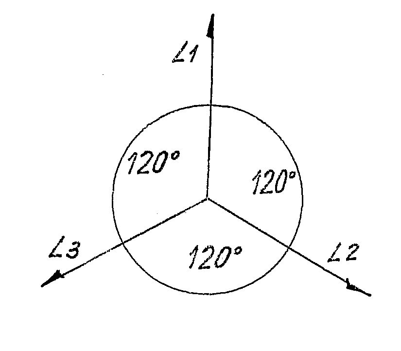
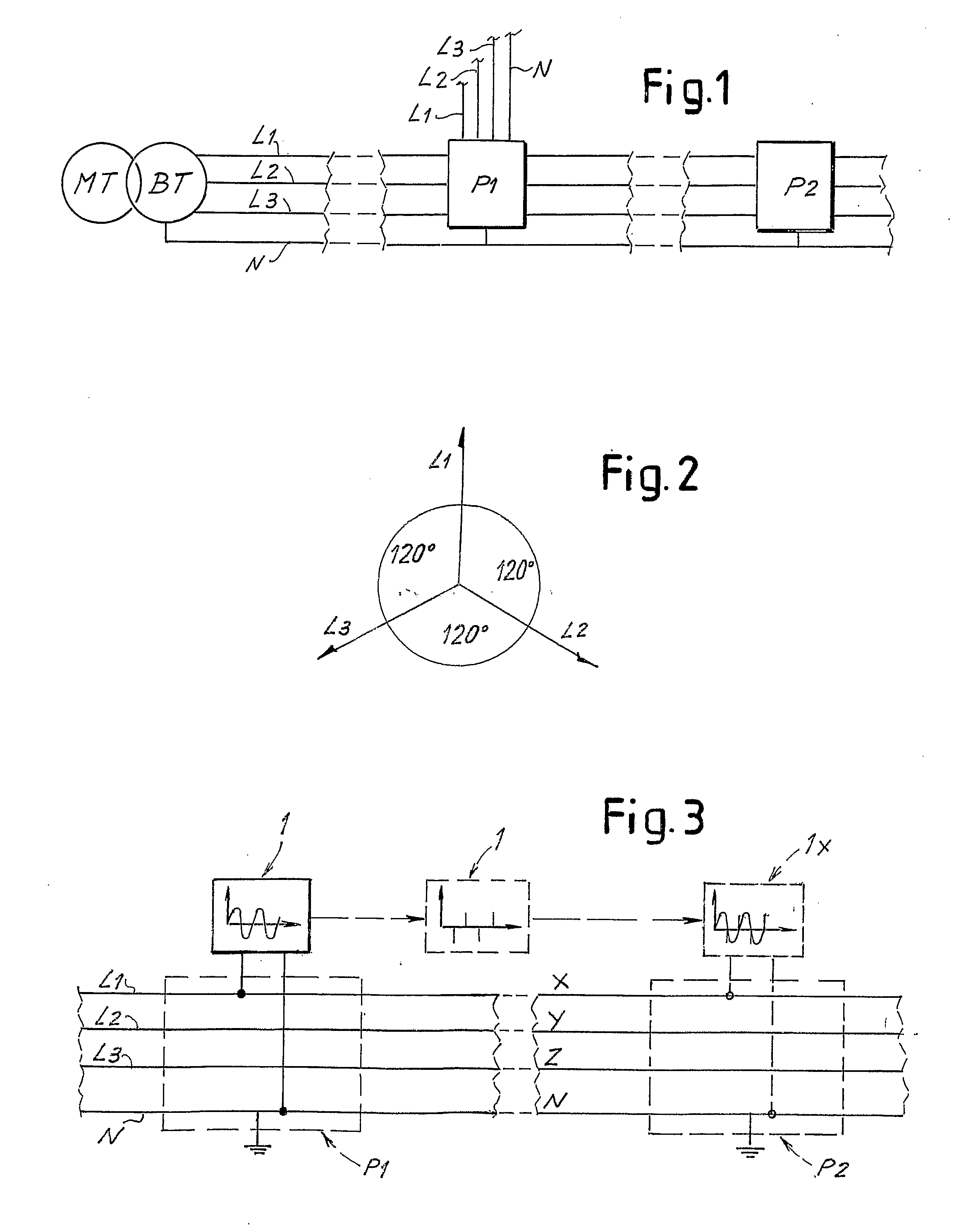
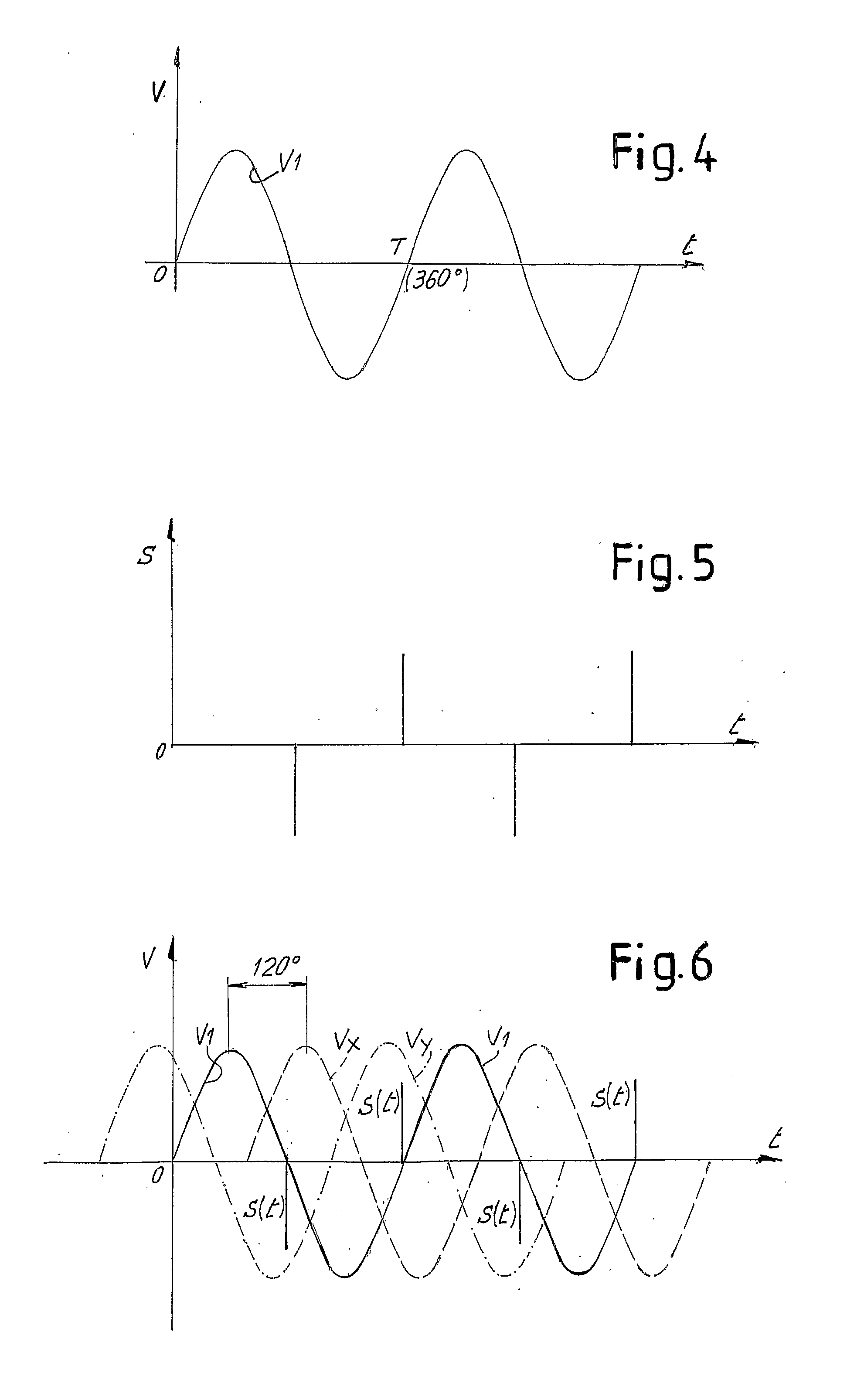
[0047]FIG. 1 schematically shows an MV / LV (medium voltage / low voltage) transformer connecting a medium voltage three-phase network to a low voltage three-phase network for electrical energy distribution. The low voltage three-phase network has three phases L1, L2, L3 and neutral N. The phase voltages are phase-shifted by 120 electrical degrees, as shown schematically in FIG. 2 in vectorial form. The low voltage distribution network can even be very complex and have a plurality of junction or interconnection nodes or points. In the simplified diagram in FIG. 1 two interconnection or junction points P1 and P2 are shown. In practice, these can be constituted by interconnection boxes, in which sections of distribution lines to be interconnected with one another converge. Each phase L1, L2, L3 at input and output of each of the interconnection points P1, P2 is in actual fact constituted by a bundle of cables in an adequate number to withstand the maximum current to be delivered through t...


PUM


Abstract

A method and device for determining the phases in a multi-phase electrical system includes detecting a first waveform on a phase of the multi-phase system In a first position of the multi-phase electrical system timed data is stored, synchronized with the first waveform. A second waveform is detected in a second position of the multi-phase electrical system, on an indeterminate phase of the system. Data is obtained relative to the phase on which the second waveform was read on the basis of the phase shift between the timed data and the second waveform.

Description

TECHNICAL FIELD[0001]The present invention relates to a phase detector device and a method for detecting a phase in a multi-phase electrical system, typically a three-phase system.BACKGROUND OF THE INVENTION[0002]In electrical energy distribution systems in urban areas, interconnection lines connect the nodes of a complex network constituted by transformer stations, in which medium to low voltage transformers supply energy to the network, and by junction or interconnection boxes, in which several lines are interconnected. The distribution system is three-phase and the distribution lines contain a plurality of cables for each phase. This is necessary in view of the high current transmitted along the lines.[0003]The cables of the various phases forming a line are often impossible to distinguish and are distributed in a disorderly manner. Identifying the phase to which one of these cables belongs is consequently a difficult and dangerous operation. In fact, work often has to be carried...

Claims


Application Information

Patent Timeline
IPC IPC(8): G01R25/00
CPCG01R29/18
Inventor TAZZARI, DAVIDEVERNIA, FILIPPO
Owner ABB (SCHWEIZ) AG
Learn More