Differential signal transmission cable and method for compensating length offset thereof

a technology of differential signal transmission and transmission cable, which is applied in the direction of waveguides, high frequency circuit adaptations, non-metallic protective coating applications, etc., can solve the problem of reducing the signal transmission quality

Inactive Publication Date: 2010-09-23
HON HAI PRECISION IND CO LTD
View PDF3 Cites 22 Cited by
  • Summary
  • Abstract
  • Description
  • Claims
  • Application Information

AI Technical Summary

Problems solved by technology

However, layout of electrical elements positioned on a printed circuit board normally cause the first and second transmission lines unequal in length, generating different transmission time for the differential signal

Method used


Image

  • Differential signal transmission cable and method for compensating length offset thereof
  • Differential signal transmission cable and method for compensating length offset thereof
  • Differential signal transmission cable and method for compensating length offset thereof

Examples


first embodiment

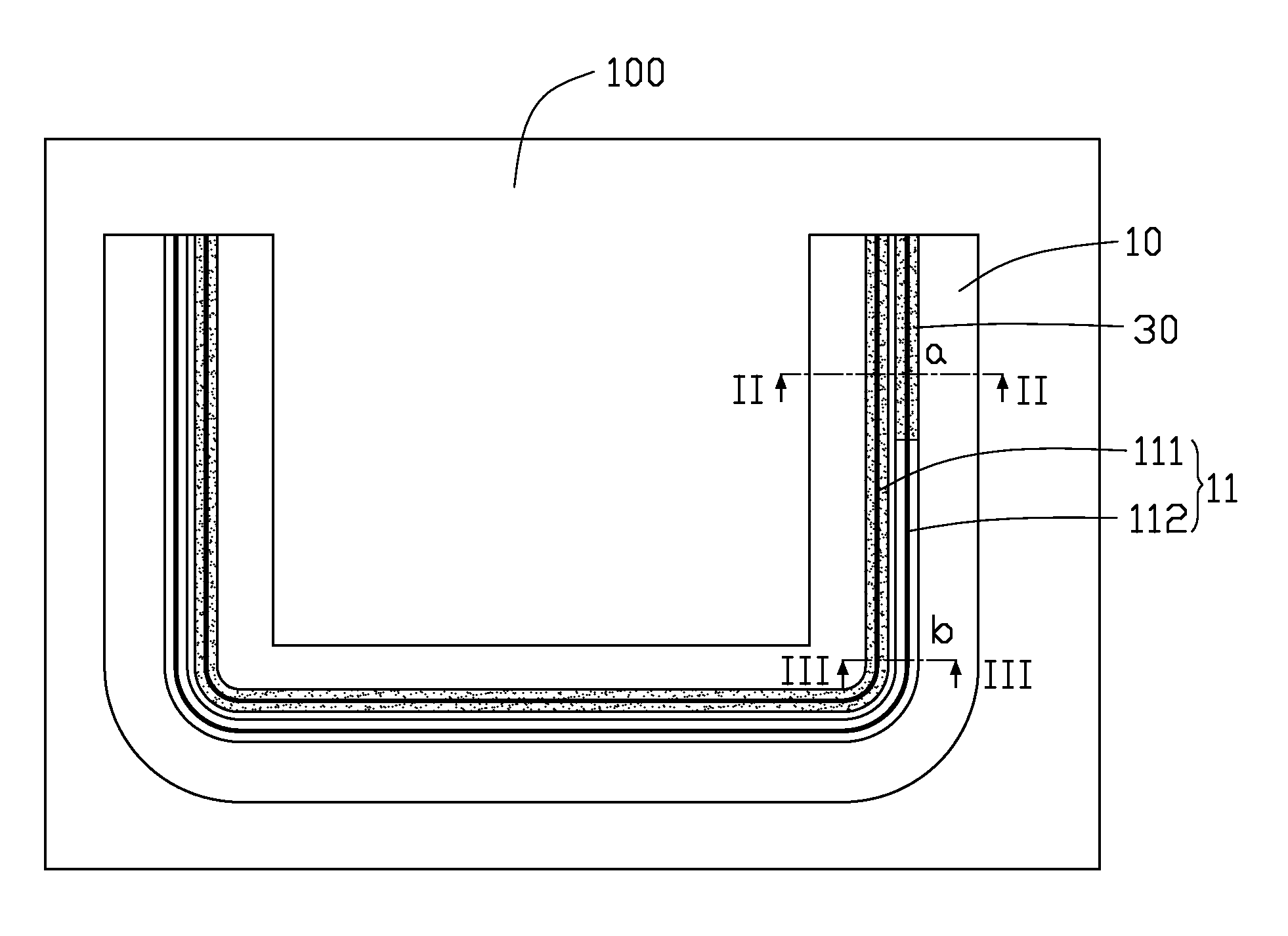
[0019]Referring to FIG. 6, a method for compensating a length offset between the first transmission line 111 and the second transmission line 112 includes the following.

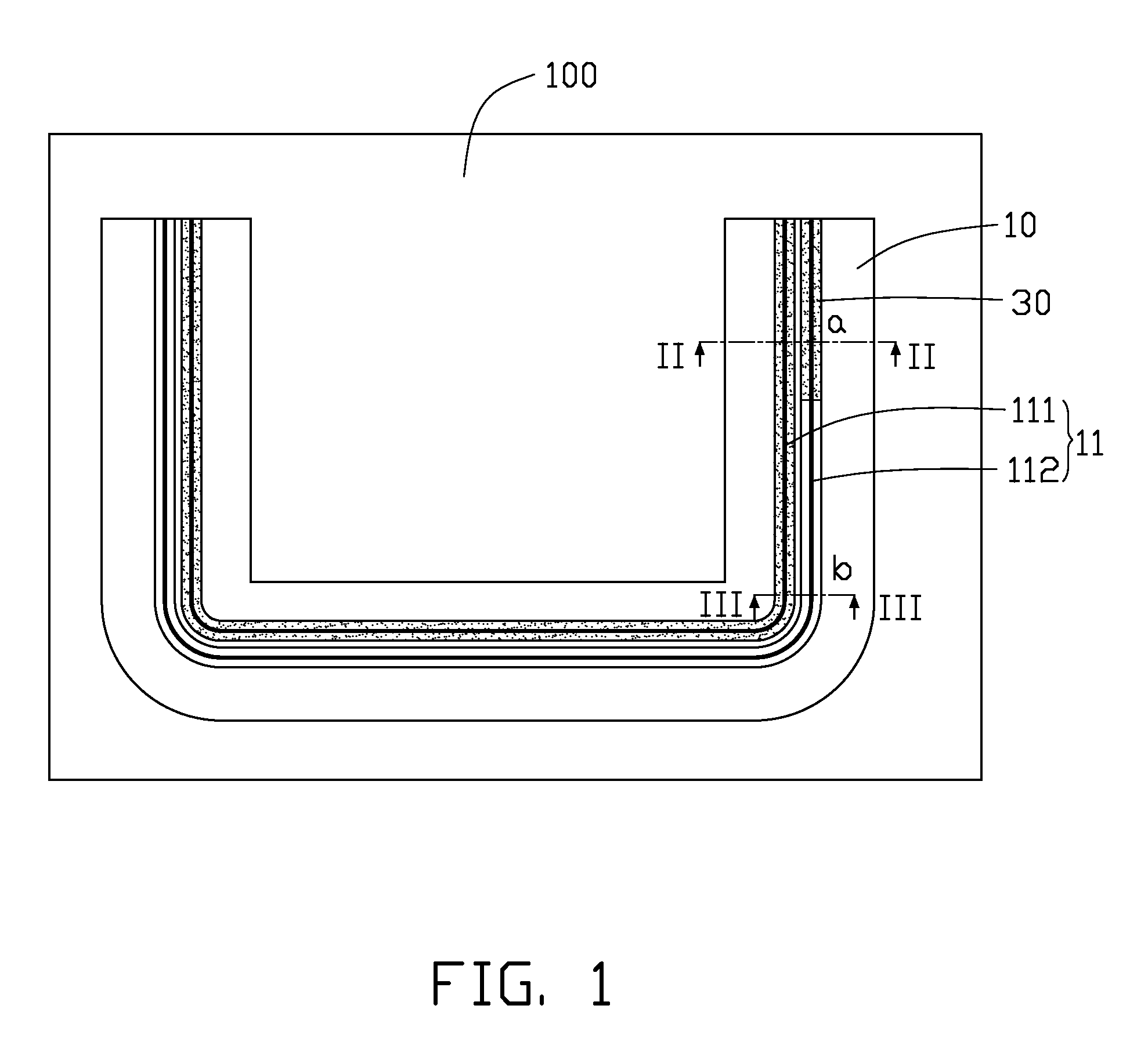
[0020]In step S61, the solder mask 30 is disposed on the outside surface of the first transmission line 111.

[0021]In step S62, the lengths of the first transmission line 111 and the second transmission line 112 are measured.

[0022]In step S63, the transmission speed of the first signal in the first transmission line 111 is calculated according to formula (1).

[0023]In step S64, the transmission time t1 of the first signal in the first transmission line 111 is calculated according to formula (2).

[0024]In step S65, a relationship between the length percent X of the first portion of the second transmission line 112 having the solder mask 30 and the length percent Y of the second portion of the second transmission line 112 without the solder mask 30 are calculated according to formula (3).

[0025]In step S66, the solder mask...

second embodiment

[0026]Referring to FIG. 7, a method for compensating a length offset between the first transmission line 111 and the second transmission line 112 includes the following.

[0027]In step S71, lengths of the first transmission line 111 and the second transmission line 112 are measured.

[0028]In step S72, the transmission speed V2 of the second signal in the second transmission line 112 is calculated according to formula (1).

[0029]In step S73, the transmission time t2 of the second signal in the second transmission line 112 is calculated according to formula (2).

[0030]In step S74, a relationship between the length percent X of the first transmission line 111 having the solder mask 30 and the length percent Y of the first transmission line 111 without the solder mask 30 are calculated according to formula (3).

[0031]In step S75, the solder mask 30 is disposed on the outside surface of the first transmission line 111 according to the length percents X and Y.


PUM


Abstract

A compensation method compensates for a length offset between a first transmission line and a second transmission line of a differential signal transmission. The compensation method includes calculating a transmission speed of a first signal in the first transmission line, measuring lengths of the first and second transmission lines, calculating a transmission time of the first signal in the first transmission line, and calculating a relationship between permittivity values of the first and second transmission lines. The compensation method further changes the permittivity values of the first and second transmission lines according to the relationship.

Description

BACKGROUND[0001]1. Technical Field[0002]The present disclosure relates to differential signal transmission, and particularly to a differential signal transmission cable and a method for compensating a length offset of the differential signal transmission cable.[0003]2. Description of the Related Art[0004]Generally, common-mode noise in signals is rejected by using differential signal transmission in a differential signal transmission cable that has a first transmission line and a second transmission line. For high transmission quality, a differential signal pair reach reception terminals of the first and second transmission lines at substantially the same time so as to have the same phase. However, layout of electrical elements positioned on a printed circuit board normally cause the first and second transmission lines unequal in length, generating different transmission time for the differential signal pair. Popular length compensation methods for differential signal transmission c...

Claims


Application Information

Patent Timeline
IPC IPC(8): H01P3/08
CPCH05K1/024H05K1/0245H05K2201/0989H05K3/28H05K2201/0187H05K1/0248
Inventor PAI, YU-CHANGLIU, CHIEN-HUNGHSIEH, PO-CHUANLIN, PEI-CHUNHSU, SHOU-KUO
Owner HON HAI PRECISION IND CO LTD
Why Eureka
Try Eureka