System and Method for Persistent ID Flag for RFID Applications

Active Publication Date: 2010-09-23
TAIWAN SEMICON MFG CO LTD
View PDF20 Cites 4 Cited by
  • Summary
  • Abstract
  • Description
  • Claims
  • Application Information

AI Technical Summary

Benefits of technology

[0013]In accordance with another embodiment, a method for writing information in a radio frequency identification (RFID) tag is provided. The method includes setting a supply voltage for a data writing mechanism based on a value of the information being written, setting a data voltage for the data writing mechanism based on the value of the information being written, and enabling the data writing mechanism to write the information.
[0015]An advantage of an embodiment is that the use of a dual-level power system helps to ensure that the reading and writing of volatile information is robust.
[0016]A further advantage of an embodiment is that a power level detection system is included to help prevent loss of data due to unexpected loss of power.
[0017]Yet another advantage of an embodiment is that once sufficient charge is accumulated, the storage of the volatile information stops, thereby helping to ensure that the volatile information is not corrupted by an unexpected loss of power and that a desired persistence of the volatile information is achieved.
[0018]Another advantage of an embodiment is that the use of a single read / write (charge & discharge) path (DRAM-like Pass Gate) may lower the risk of data lost and extend the persistence time when compared with the prior art.

Problems solved by technology

Since passive RFID tags do not contain a power source and derive their power from received transmissions, the passive RFID tags will typically not be able to derive any power to operate when transmissions are not received.
Therefore, volatile information, such as data stored in dynamic memory memories, including dynamic random access memory, registers, latches, so on, for example, will be lost after transmissions are no longer received at the passive RFID tags, resulting in a loss of power.
The handshake operation may take a finite amount of time.
However, since TAG3115 is a passive RFID tag, once TAG3115 moves outside of communications range of RFID reader 105, it may no longer be able to derive power needed to maintain volatile information stored therein.

Method used


Image

  • System and Method for Persistent ID Flag for RFID Applications
  • System and Method for Persistent ID Flag for RFID Applications
  • System and Method for Persistent ID Flag for RFID Applications

Examples


Embodiment Construction

[0035]The making and using of the embodiments are discussed in detail below. It should be appreciated, however, that the present invention provides many applicable inventive concepts that can be embodied in a wide variety of specific contexts. The specific embodiments discussed are merely illustrative of specific ways to make and use the invention, and do not limit the scope of the invention.

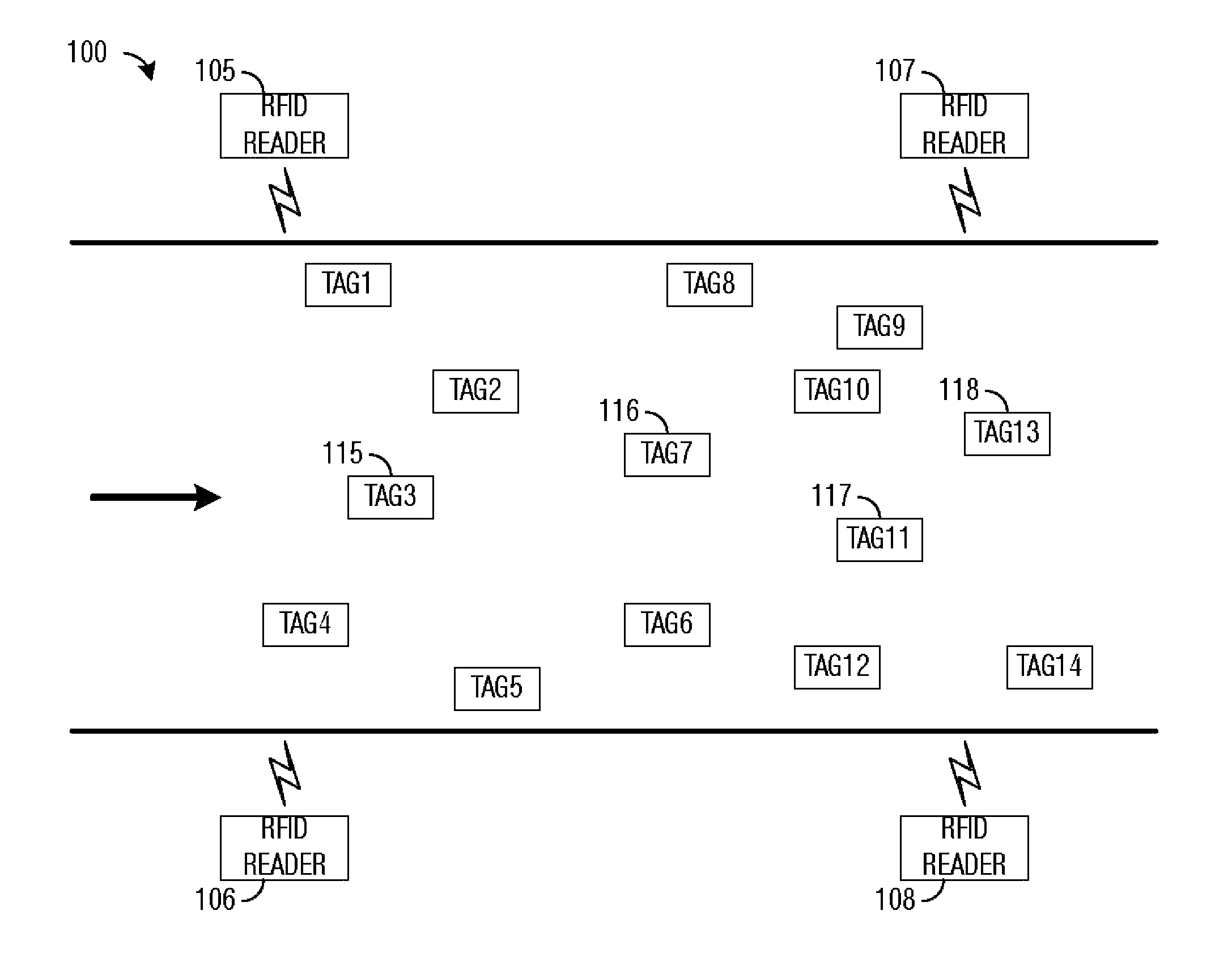
[0036]The embodiments will be described in a specific context, namely a passive RFID tag with a desired RFID data register persistence of two (2) or more seconds. The invention may also be applied, however, to other passive RFID tags with other desired persistence values. Additionally, the invention may also be applied to other applications wherein there is a desire to maintain volatile information for a specified amount of time without having to provide a power supply.

[0037]FIG. 3 is a diagram of a circuit 300 for use in storing volatile information in a passive RFID tag. Circuit 300 may be use...


PUM


Abstract

A system and method for persistent ID flag for RFID applications includes a method for operating an RFID tag. The method includes measuring a voltage potential of a supply voltage for the RFID tag, and turning on a pass gate that couples a memory cell to a data line used for reading or writing data, if the voltage potential is greater than a first threshold. An accumulated charge on the memory cell is also measured, and both the voltage potential and the accumulated charge are used to generate a control signal to set a state of the pass gate. The pass gate is turned off if the control signal is a true value.

Description

[0001]This application claims the benefit of U.S. Provisional Patent Application Ser. No. 61 / 160,838, filed on Mar. 17, 2009, and entitled “System and Method for Persistent ID Flag for RFID Applications,” which application is incorporated herein by reference.TECHNICAL FIELD[0002]The present invention relates generally to radio frequency identification (RFID) devices, and more particularly to a system and method for persistent ID flag for RFID applications.BACKGROUND[0003]In general, RFID is a system that allows for automatic identification of RFID tags and things attached thereto. An RFID system usually includes a number of RFID tags that may be used to identify and / or track objects, persons, animals, products, inventory, and so forth, and at least one RFID reader that may be used to detect and read RFID tags. Typically, there may be two types of RFID tags: active RFID tags that contain a power source (a battery, for example) and passive RFID tags that do not contain a power source,...

Claims


Application Information

Patent Timeline
IPC IPC(8): H04Q5/22
CPCG06K19/07749
Inventor HUNG, CHENG-HSIENLIN, YU-LING
Owner TAIWAN SEMICON MFG CO LTD
Why Eureka
Try Eureka