Display panel and method of repairing bright point thereof

a technology of a display panel and a bright point, which is applied in the manufacture of electrode systems, electric discharge tubes/lamps, instruments, etc., can solve the problems of bright point defects on the display, electrical leakage via foreign matter, and malfunction of molecules, so as to improve the effectiveness of bright point defects and reduce the transmittance of liquid crystal layers.

Active Publication Date: 2010-09-23
AU OPTRONICS CORP
View PDF5 Cites 24 Cited by
  • Summary
  • Abstract
  • Description
  • Claims
  • Application Information

AI Technical Summary

Benefits of technology

[0007]The present disclosure provides a display panel and a method for repairing a bright point through applying energy light beams to the patterned color layer of a bright point defect. The energy light beam causes expansion of the patterned color layer which fills the cell gaps either completely or partially such that it lowers the transmittance of the liquid crystal layer and turns the bright point to a dark or a grey point. This method improves the effectiveness of repairing bright point defects in comparison to the laser blade signal cut-off method described above.

Problems solved by technology

However, during the manufacturing process of an LCD panel, any foreign matters, particles, or contaminants which adhere onto the color filter substrate or the array substrate, or are mixed in the liquid crystal layer, would affect the operation of the TFT by causing adjacent liquid crystal molecules to malfunction which become bright point (or dark point) defects on the display.
However, when the particle of the foreign matter is too large or the position of the foreign matter is too close to the wires of the array substrate, short circuiting the TFTs or breaking the signals connecting to the TFTs may still result in electric leakage via foreign matter, making the bright point defect repair ineffective.
Also, prior art repairing methods cannot repair the bright point defect caused by surface scratches of the substrates as well as prevent the foreign matters from migrating to other sub-pixel regions after the repairs which introduces new bright point defects or shifts the existing bright point defects.

Method used


Image

  • Display panel and method of repairing bright point thereof
  • Display panel and method of repairing bright point thereof
  • Display panel and method of repairing bright point thereof

Examples


second embodiment

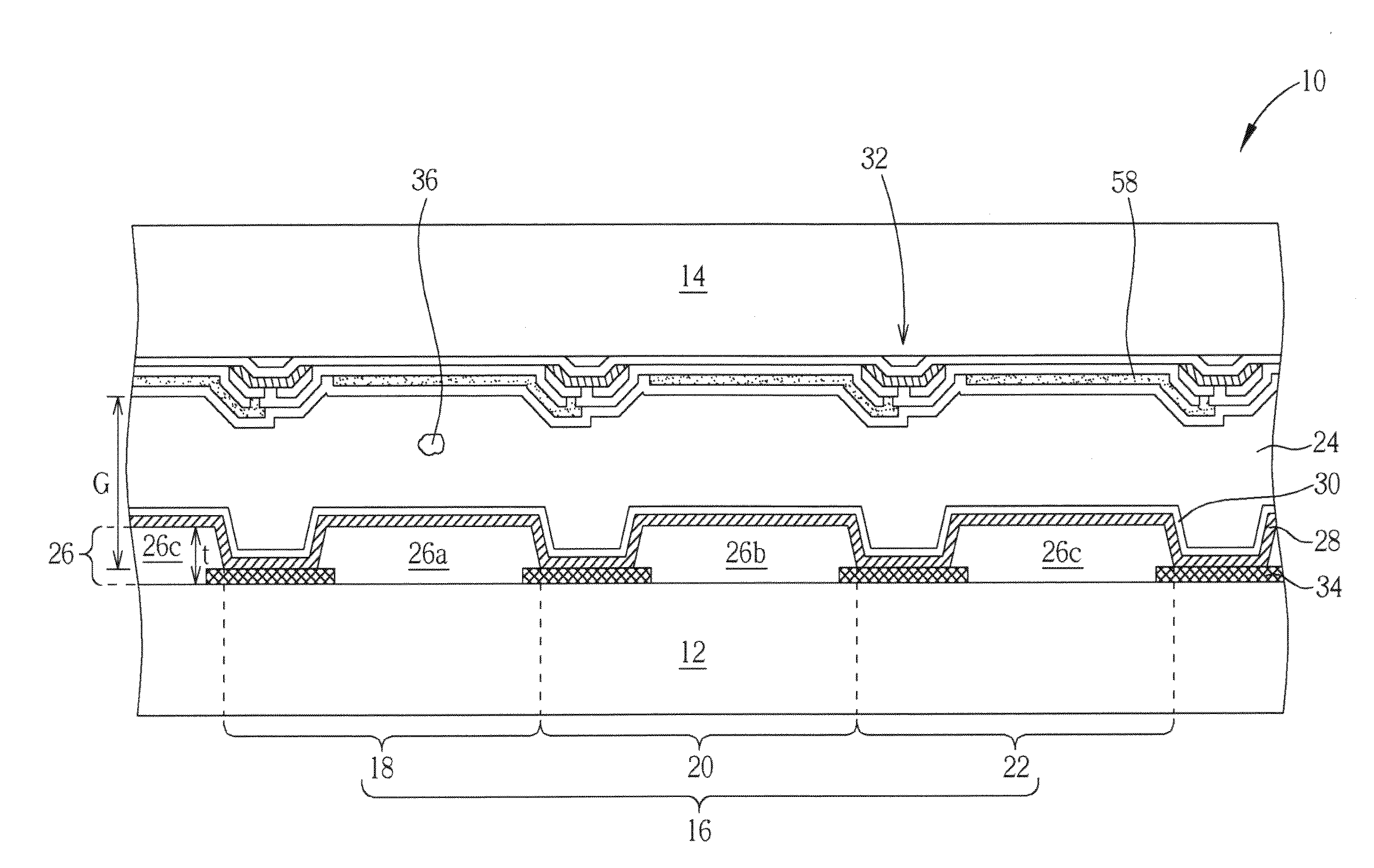
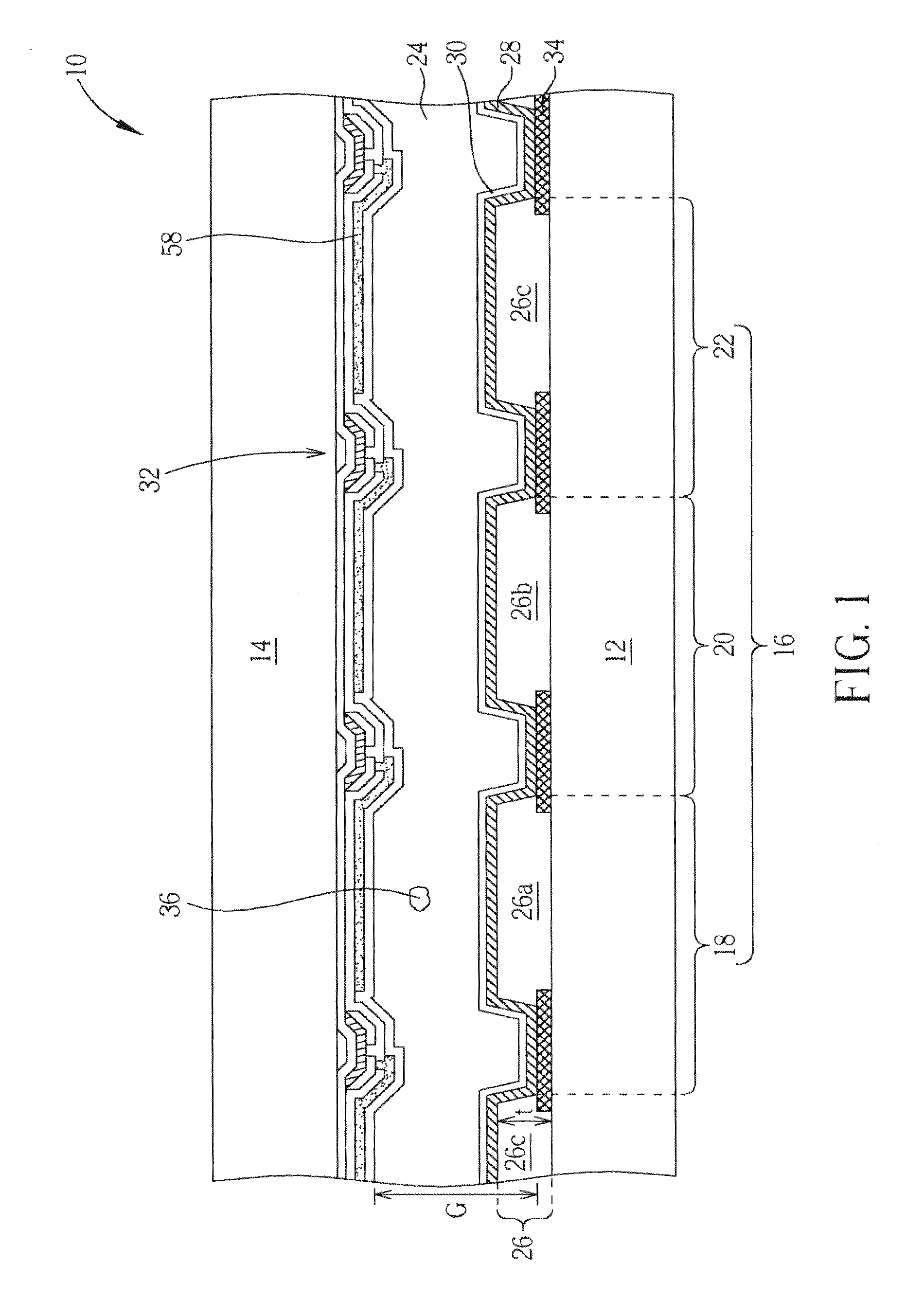
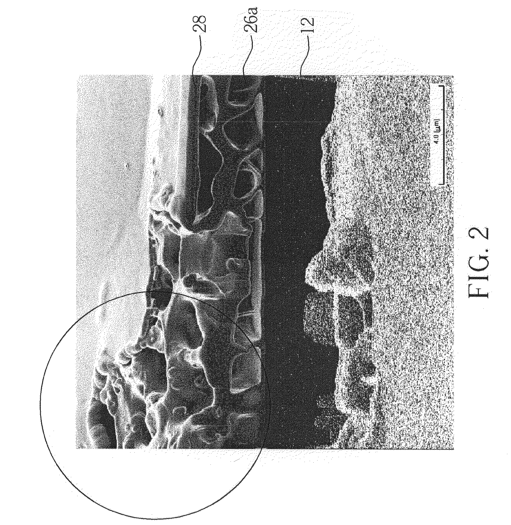
[0033]Referring to FIG. 7, FIG. 7 is a cross-sectional view of the display panel of the present disclosure; those components identical with the components of FIG. 4 share the same symbols. As shown in FIG. 7, the display panel 70 of the present disclosure is a color filter on array (COA) panel with a color filter 26 disposed on an array substrate such that the color filter 26 and the transistor 32, or other array units are all disposed on the surface of the second substrate 14. The display panel 70 of the present disclosure has been repaired using the repairing process of the present disclosure. Therefore, before the repairing process, if a bright point defect is detected at the first sub-pixel region 18, the repairing process of the present disclosure would apply a short term low energy light beam to the first patterned color layer 26a, causing expansion of the first patterned color layer 26a and forming porous structures 42, 44, 46, while the thickness of the expansion is at least...

third embodiment

[0034]Referring to FIG. 8, FIG. 8 is the cross-sectional view of the display panel of the present disclosure; those components identical with the components of FIG. 4 share the same symbols. As shown in FIG. 8, a display panel 80 of the present disclosure is an array on array color filter (AOC) panel in which the transistors 32, or other array units are disposed on the same surface of the color filter substrate as the color filter 26, as illustrated by the first substrate 12 in the figure. In the present embodiment, array units such as the transistors 32 and the pixel electrodes 58 are disposed on the surface of the color filter 26. When the repairing process on the first pixel region 18, an energy light beam (not illustrated) scans the entire first pixel region 18 in sequence; therefore, most of the first patterned color layer 26a in the first sub-pixel region 18 expands evenly and exhibits porous structures 42, 44, 46. The thickness of the first patterned color layer 26a also expa...


PUM

PropertyMeasurementUnit
energyaaaaaaaaaa
energyaaaaaaaaaa
thicknessaaaaaaaaaa

Abstract

A display panel has a portion of a color filter or patterned color layer with a thickness of at least half of the cell gap of the display panel, wherein the repair method includes providing a energy light beam to the portion of the color filter or the patterned color layer in the sub-pixel region with a bright point defect to make the portion of the color filter or patterned color layer have porous structure so that bright point is repaired to become a grey point or a dark point

Description

BACKGROUND OF THE DISCLOSURE[0001]1. Field[0002]The present disclosure relates to a display panel and a method for repairing a bright point; particularly to a method for repairing a bright point using an energy light beam which excites a color filter and the display panel with color filters of various thicknesses.[0003]2. Description of the Prior Art[0004]When comparing with a traditional non-flat display, such as a cathode ray tube (CRT) display, the flat display panel possesses light weight and thin profile characteristics. Such device has now become a mainstream in the display market, and is widely applied in televisions, monitors of personal computers, and portable electronic products such as cell phones, digital cameras, and music players.[0005]Some of the most common display panels include liquid crystal displays (LCD), plasma displays, and electroluminance displays. In the case of LCD, it is comprised of an LCD panel and a backlight module. The backlight module is used to sup...

Claims


Application Information

Patent Timeline
Patent Type & Authority Applications(United States)
IPC IPC(8): G02F1/1335H01J9/50
CPCH01J9/50G02F1/133514G02F1/1309Y02W30/82
Inventor YIN, HSUEH-MINHUANG, HSIN-CHANGLIN, JUNG-HSIANGHUANG, SHEN-YI
Owner AU OPTRONICS CORP
Why Eureka
Try Eureka