Discharge lamp drive device, discharge lamp drive method, light source device, and projector

a discharge lamp and drive device technology, applied in the direction of energy-saving lighting, instruments, sustainable buildings, etc., can solve the problems of difficult fused concaves and convexes at the tips of the electrodes, low fusing energy generation, and decreased fusion quantity so as to prevent the generation of flicker fk, the flatness of the projections 532p and 542p is further promoted, and the effect of decreasing the quantity

Inactive Publication Date: 2010-09-23
SEIKO EPSON CORP
View PDF9 Cites 12 Cited by
  • Summary
  • Abstract
  • Description
  • Claims
  • Application Information

AI Technical Summary

Benefits of technology

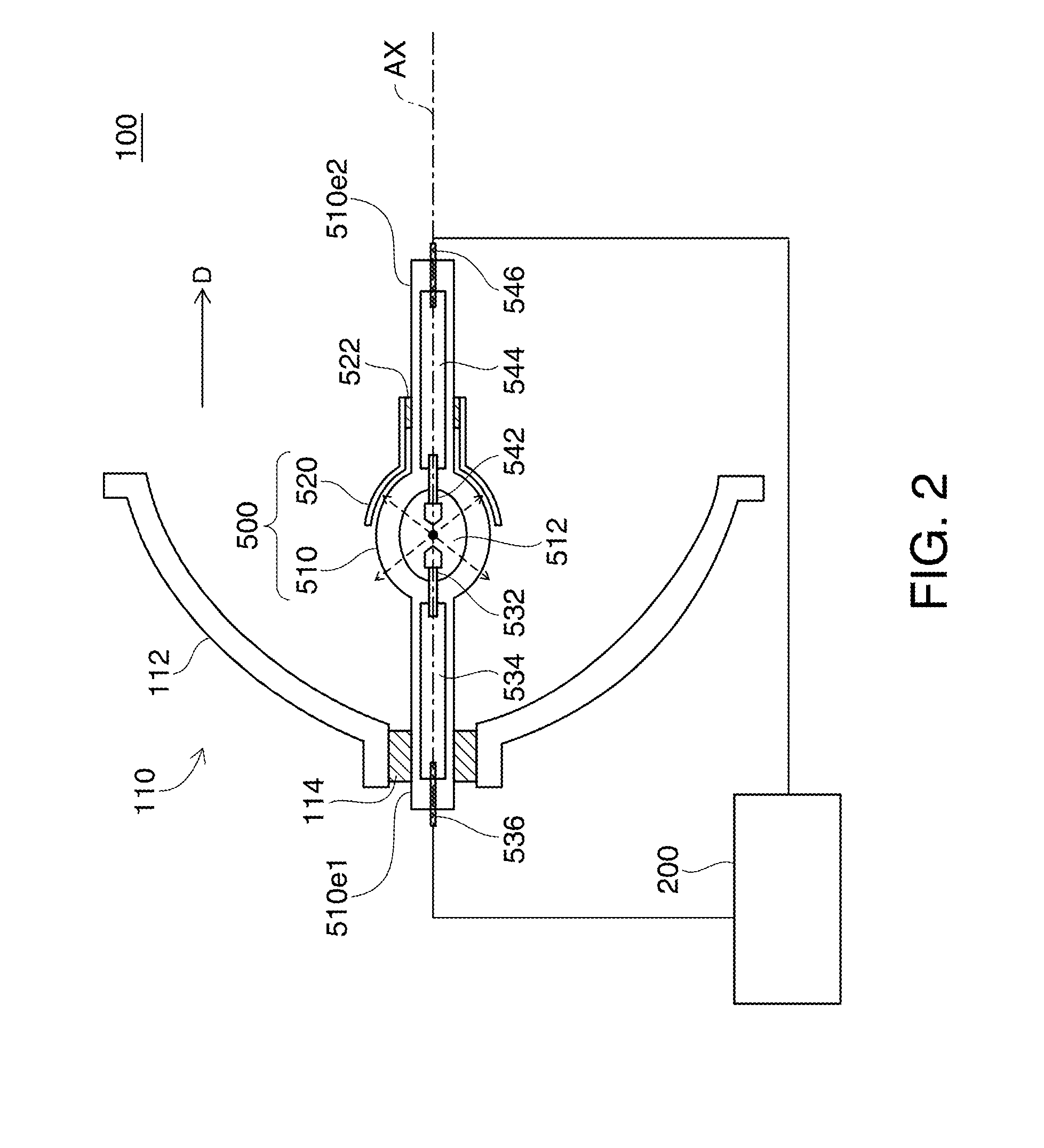
[0092]FIG. 8 shows comparison between arc generation condition in this embodiment and that in related art. As illustrated in part (A) in FIG. 8, the respective electrodes 532 and 542 repeat fusion and solidification with sufficient fusion quantity by alternating rated power before switching the drive of the discharge lamp 500 from the rated power mode to the low power mode. In the figure, the fused area is expressed as hatched area, and wide areas of the tips of the electrodes 532 and 542 are fused. The duty ratio of the alternating current in this step is 50:50.
[0093]Initially, the arc generation condition in the related art is discussed. As illustrated in the left part in the figure, the alternating current flowing in the electrodes 532 and 542 immediately decreases by power reduction immediately after switching from the rated power mode to the low power mode. Thus, the projections 532p and 542p (the same reference numbers as those in this embodiment are given to the electrodes and projections in the related art) are not sufficiently fused as shown in part (B) in FIG. 8. In this case, the tips of the projections 532p and 542p do not become spherical as in the rated power mode but become flat. When the tips of the projections 532p and 542p are flat, arc is generated at random positions on the flat projections 532p and 542p. As a result, flickers FK are produced.
[0094]After elapse of long time (such as 1 hour) from the switching, the fusion quantity of the projections 532p and 542p is further decreased, and flatness of the tips of the projections 532p and 542p is further promoted. The tips of the projections 532p and 542p become flat as shown in part (C) in FIG. 8. As a result, arc is generated at a number of positions on the projections 532p and 542p, and more flickers FK are produced.
[0095]On the other hand, the duty ratio of the alternating current is steppedly changed immediately after switching to the low power mode in this embodiment as illustrated in part (D) in FIG. 8. Thus, the fusion quantity at the tips of the projections 532p and 542p can be maintained equivalent to that in the rated power mode by increasing the period for operating the first electrode 532 with anode and the period for operating the second electrode 542 with anode in one cycle shown in FIG. 5 (T1+T2: see FIG. 5). As a result, generation of flickers FK can be prevented.
[0096]According to this embodiment, low alternating current for obtaining low power is used in one cycle Ta while varying the duty ratio of the alternating current. Thus, the areas of temperature increase on the projections 532p and 542p are narrowed, and the projections 532p and 542p obtain long and narrow shape. In this case, the long and narrow projections 532p and 542p can be fused by low alternating current even after elapse of long time as illustrated in part (E) in FIG. 8, and thus stable arc is generated from the tips of the long and narrow projections 532p and 542p. As a result, generation of flickers FK can be prevented even after elapse of long time.
[0097]Modified examples of the first embodiment are hereinafter described.

Problems solved by technology

According to the related-art technology discussed above, however, the quantity of fusion at the tips of the electrodes decreases when the discharge lamp is driven by power lower than rated power.
In this case, only low fusing energy is generated, and the concaves and convexes produced at the tips of the electrodes are difficult to be fused.
According to the structure of the third aspect, however, actual reduction of the alternating power supplied to the discharge lamp is delayed by the delay time.

Method used


Image

  • Discharge lamp drive device, discharge lamp drive method, light source device, and projector
  • Discharge lamp drive device, discharge lamp drive method, light source device, and projector
  • Discharge lamp drive device, discharge lamp drive method, light source device, and projector

Examples


first embodiment

A-5. Modified Examples of First Embodiment

[0097]Modified examples of the first embodiment are hereinafter described.

modified example 1 of first embodiment

[0098]FIG. 9 is a timing chart showing modulation of the duty ratio of the alternating current to be outputted to the discharge lamp according to a modified example 1 of the first embodiment. In the first embodiment, the period of modulation is the one cycle Ta constituted by 16 division terms. According to the modified example 1, however, the period of modulation contains two cycles Ta each of which has the same cycle pattern as that of the first embodiment. It is possible to determine the period of modulation as a period containing three, four or more plural cycles Ta.

[0099]The maximum period for modulation may be determined as period until the end of the low power mode. According to this structure, the fusion quantity in the low power mode can be maintained at a large quantity even after elapse of long time from power reduction. In this case, generation of flicker can be securely prevented for a longtime after power reduction.

modified example 2 of first embodiment

[0100]According to the structure in the modified example 1 shown in FIG. 9, the change pattern of the duty ratio of the initial cycle Ta is the same as the change pattern of the duty ratio of the next cycle Ta. However, the change of the duty ratio for each step may be increased with elapse of time by using a change pattern of the later cycle Ta different from the change pattern of the earlier cycle Ta.

[0101]FIG. 10 is a timing chart showing modulation of the duty ratio of the alternating current to be outputted to the discharge lamp in a modified example 2 of the first embodiment. As shown in the figure, the change for each step is 5% in the initial cycle Ta, but is increased to 6% in the next cycle Ta. This structure has two cycles Ta, but may contain three or more cycles Ta whose change for each step increases as in the later cycles Ta. In this structure, the change for changing the duty ratio for each step increases with elapse of time, and thus stable generation of arc and ther...


PUM


Abstract

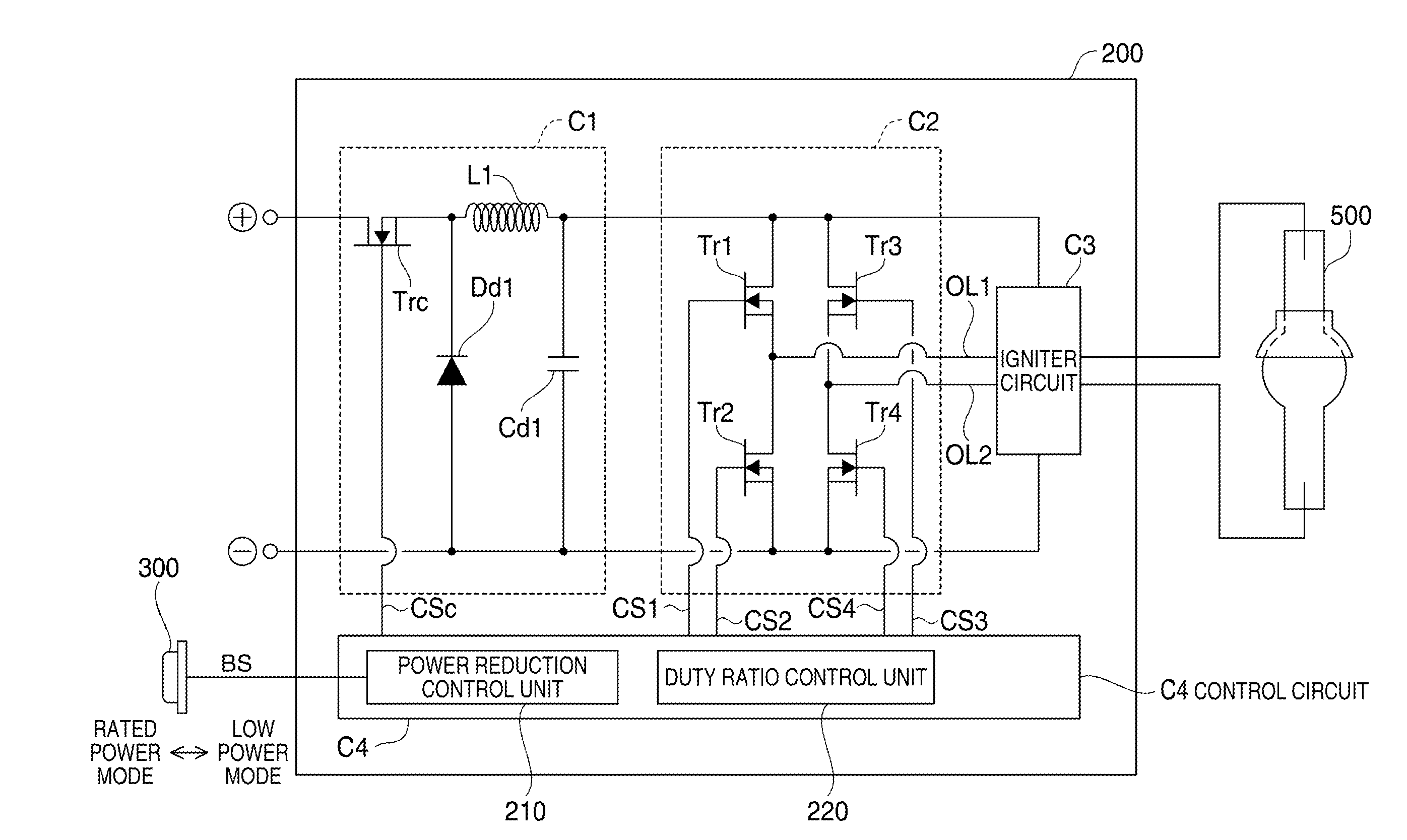
A discharge lamp drive device for driving a discharge lamp including a first electrode and a second electrode, include: a power supply unit which supplies alternating power to the discharge lamp by inputting alternating current between the first electrode and the second electrode, wherein the power supply unit includes a power reduction control unit which reduces the alternating power from a first level to a second level lower than the first level, and a duty ratio control unit which steppedly varies duty ratio of the alternating current in a predetermined period at the time of reduction of the alternating power.

Description

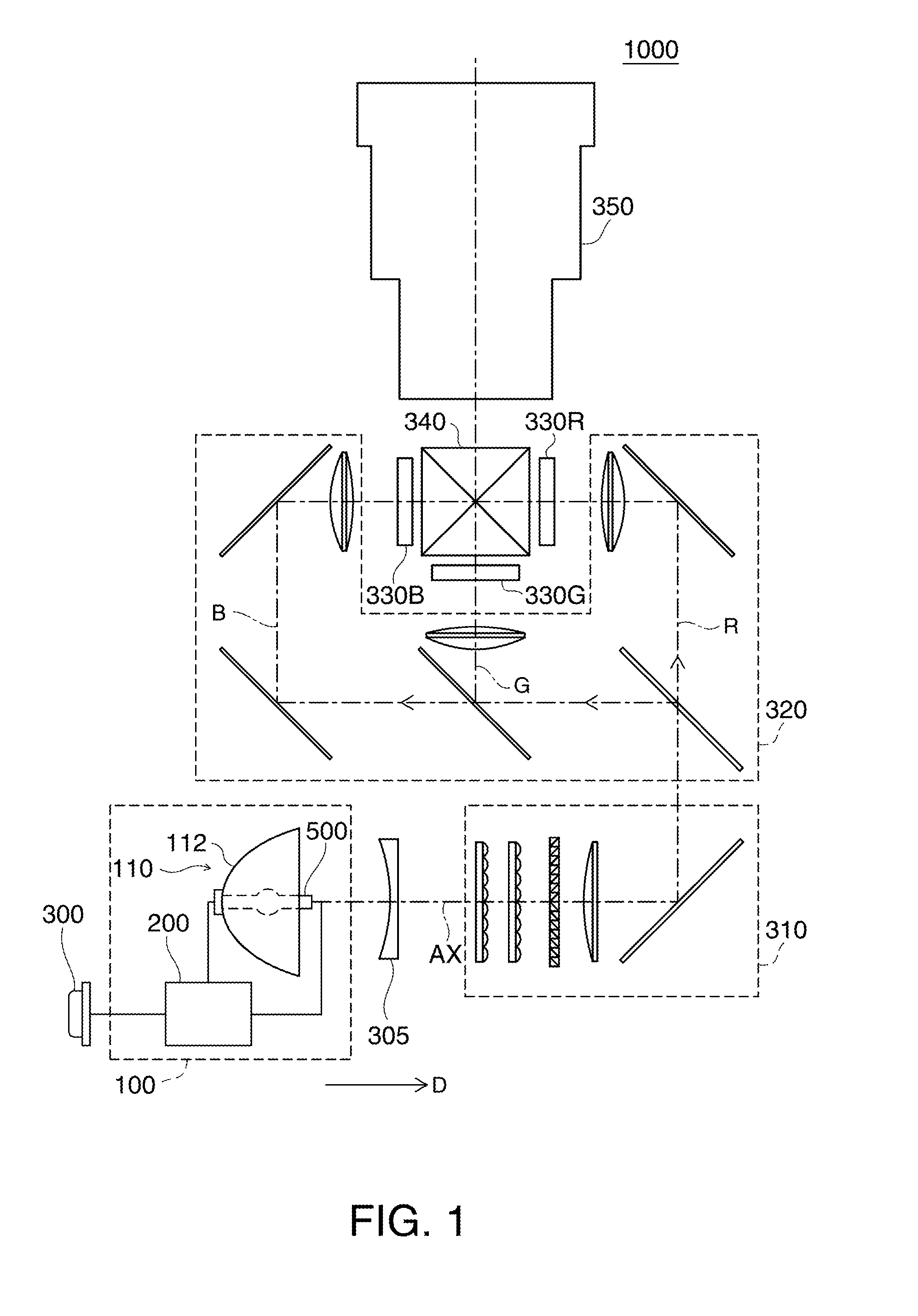
BACKGROUND[0001]1. Technical Field[0002]The present invention relates to a technology of driving a discharge lamp which emits light by discharge generated between electrodes.[0003]2. Related Art[0004]A projector provided with a discharge lamp is known. This type of projector supplies alternating power to the discharge lamp to generate discharge between two electrodes provided on the discharge lamp. In addition, such a technology is known which switches alternating power supplied to the discharge lamp from rated power to low power so as to increase life and decrease power consumption of the discharge lamp (see JP-A-2000-131668). The discharge lamp emits light by generating arc between projections formed on the respective electrodes.[0005]According to the related-art technology discussed above, however, the quantity of fusion at the tips of the electrodes decreases when the discharge lamp is driven by power lower than rated power. In this case, projections having preferable shape are ...

Claims


Application Information

Patent Timeline
Patent Type & Authority Applications(United States)
IPC IPC(8): H05B41/36G03B21/20
CPCH05B41/2886G03B21/2053G03B21/2026Y02B20/202Y02B20/00
Inventor SOMA, SHIGEYASUTERASHIMA, TETSUO
Owner SEIKO EPSON CORP
Why Eureka
Try Eureka