Devices for detecting accumulation amount of particulates

Active Publication Date: 2010-09-30
NGK INSULATORS LTD
View PDF6 Cites 10 Cited by
  • Summary
  • Abstract
  • Description
  • Claims
  • Application Information

AI Technical Summary

Benefits of technology

[0028]In addition to this, the transmitting and receiving portions for electromagnetic wave are not provided in the upstream and downstream pipes. It is thus possible to prevent the reduction of sen

Problems solved by technology

However, in detection of the accumulation amount of particulates such as soot by use of microwave, absorption of carbon

Method used


Image

  • Devices for detecting accumulation amount of particulates
  • Devices for detecting accumulation amount of particulates
  • Devices for detecting accumulation amount of particulates

Examples


examples

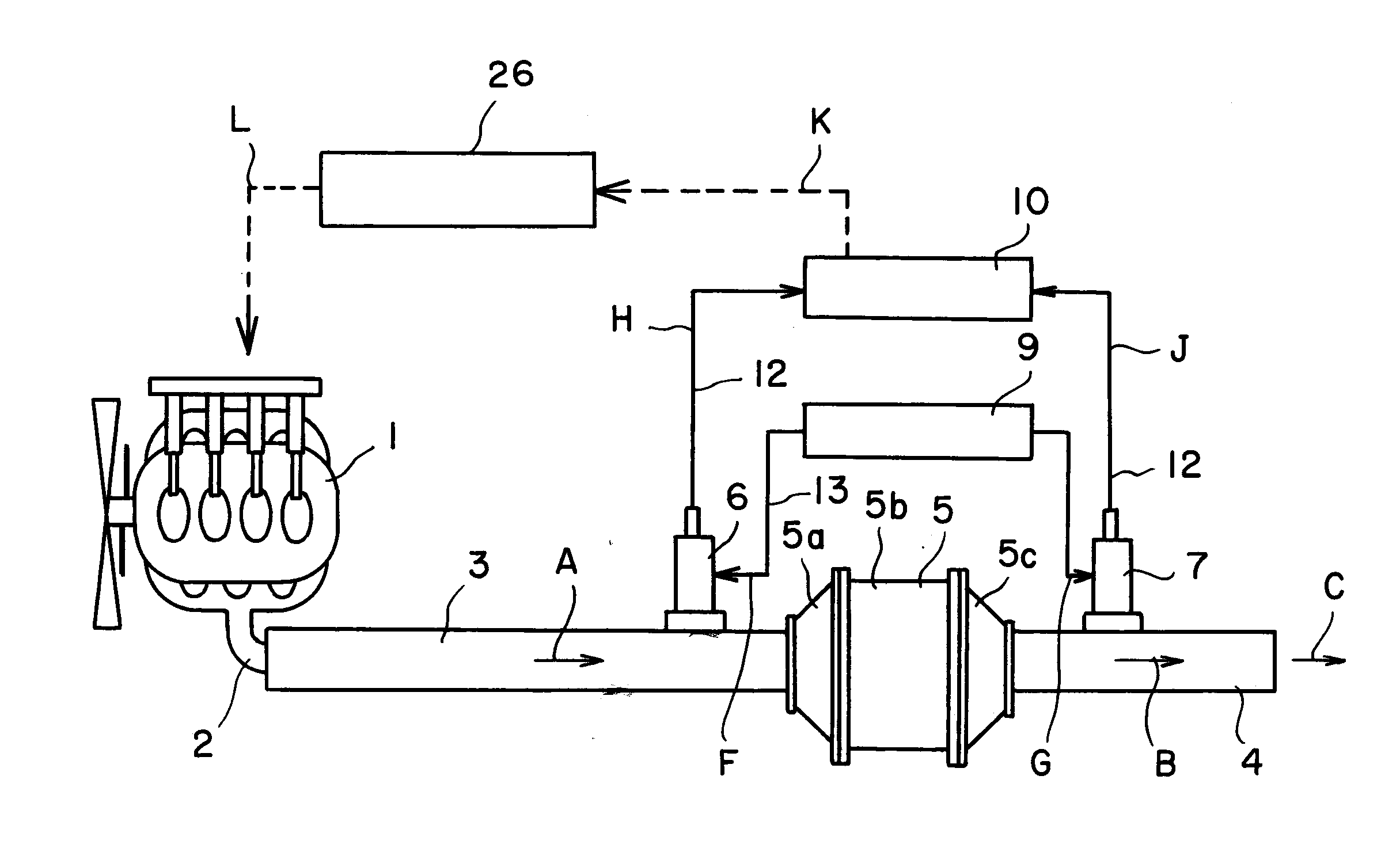
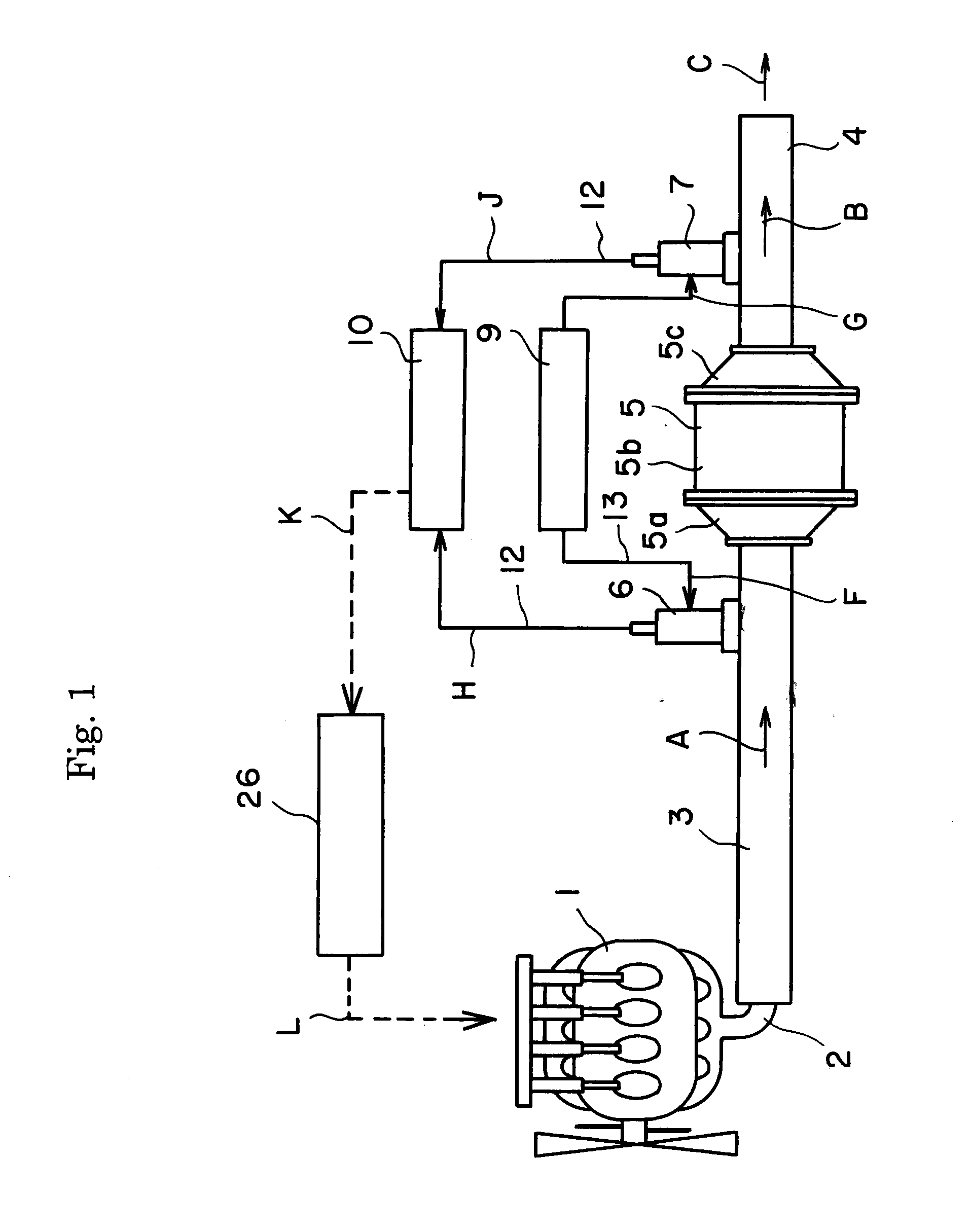
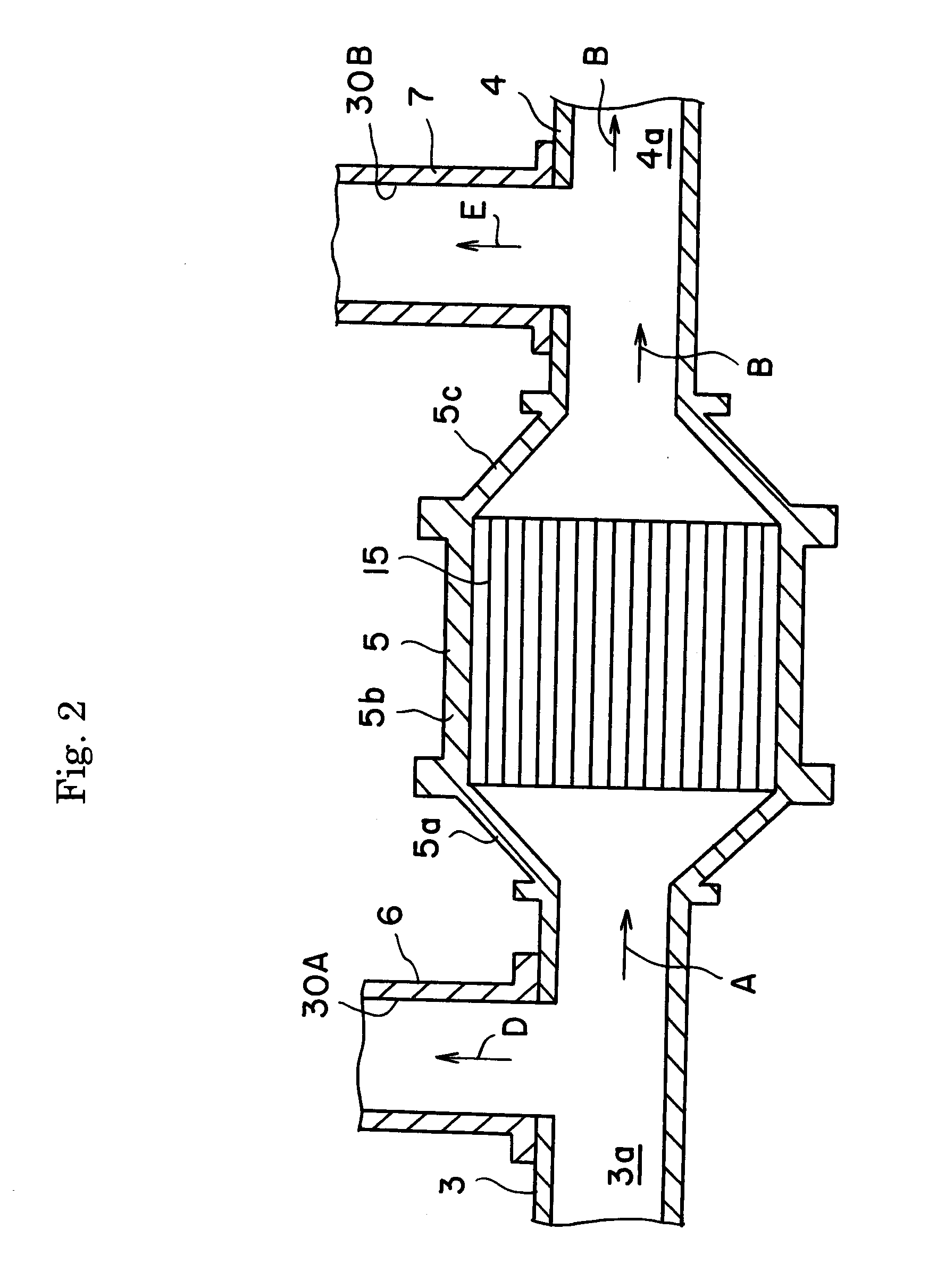
[0058]FIG. 1 schematically shows an exhaust emission control system. An exhaust pipe 2 of an exhaust manifold of a diesel engine 1 is connected to a container 5 through an upstream pipe 3. A downstream pipe 4 is provided on the downstream side of the container 5. The container 5 includes, as shown in FIG. 2, a storage part 5b with a constant inside diameter for storing a filter, an upstream connection part 5a and a downstream connection part 5c.

[0059]A filter 15 is stored within the storage part 5b of the container 5. The filter 15 is composed of a porous ceramic honeycomb structure having a number of pores regularly formed therein. A part of the pores is sealed on the exhaust gas downstream side to form inflow-side cells, and the remainder thereof is sealed on the exhaust gas upstream side to form outflow-side cells. The inflow-side cells and the outflow-side cells are formed to be alternately adjacent to each other, whereby a honeycomb-shaped wall flow structure is constituted.

[0...


PUM


Abstract

A device for detecting particulates includes: a filter; a filter container; an upstream pipe; a downstream pipe; an upstream detecting unit; and a downstream detecting unit. The upstream detecting unit has a branch flow route for receiving gas from the upstream pipe, a trapping portion, a transmitting portion for transmitting an electromagnetic wave to the trapping portion, and a receiving portion for receiving an electromagnetic wave from the trapping portion. The downstream detecting unit has a branch flow route for receiving gas from the downstream pipe, a trapping portion, a transmitting portion for transmitting an electromagnetic wave to the trapping portion, and a receiving portion for receiving an electromagnetic wave from the trapping portion. The amount of the particulates trapped in the filter is detected based on a difference between detection values of the mass of the particulates trapped in the upstream and downstream trapping portions.

Description

[0001]This application claims the benefit of Japanese Patent Application P2009-74358 filed on Mar. 25, 2009, the entirety of which is incorporated by reference.TECHNICAL FIELD[0002]The present invention relates to a device for detecting an accumulation amount of particulates, which may be used for detection of PM accumulation amount in a filter disposed in an exhaust system of an internal combustion engine such as a diesel engine or the like.BACKGROUND ARTS[0003]Toxic substances in the internal combustion engine, such as the diesel engine, are discharged as PM (particulate matter: soot composed of carbon fine particles, high-molecular weight hydrocarbon fine particles, sulfur-based fine particles such as sulfate, etc.). Since the Environmental Agency recently has considered deciding an environmental criterion with respect to fine particulates with particle size of 2.5 μm or less to more strictly regulate particulates, a development race has been performed to respond to the stricter ...

Claims


Application Information

Patent Timeline
IPC IPC(8): F01N11/00F01N3/02
CPCY02T10/47F01N11/00Y02T10/40
Inventor KONDO, JUNGOMATSUHIRO, KEIJIAOKI, KENJIKONDO, ATSUO
Owner NGK INSULATORS LTD
Why Eureka
Try Eureka