Load sensing system, working machine comprising the system, and method for controlling a hydraulic function

Active Publication Date: 2010-09-30
VOLVO CONSTR EQUIP
View PDF7 Cites 17 Cited by
  • Summary
  • Abstract
  • Description
  • Claims
  • Application Information

AI Technical Summary

Benefits of technology

[0014]According to another preferred embodiment, the system comprises a steering function. As a rule, a valve unit in the form of an orbitrol unit is used for the steering function. According to prior art, there are problems to get the orbitrol steering stable, since resonances with respect to pressure fluctuations arise. This is amplified since the hydraulic LS signal from the orbitrol unit is also oscillating. By instead reading the LS signal of the orbitrol unit via pressure sensors and setting a higher LS pressure via the electrical LS valve, a stable LS signal to the pump can be obtained, which means a filtered signal.
[0015]According to another preferred example, the system comprises a position sensor for the actuator. In this way prerequisites for end position damping are created. If the system has a separate feed pump for a function, for example for the steering function, the electrical LS signal can be used for end position damping. This means that the control unit registers that the actuator (cylinder) is approaching the end position via positions sensors. The electrical LS valve can then lower the control pressure to a suitable level, so that the maximum steering rate is reduced, which means that the operator cannot exceed a certain steering rate.
[0016]Positions sensors also create prerequisites for a power control. In certain situations, it is desired to reduce the maximum possible hydraulic power output, for example because the engine does not have the power at low rpms. The electrically controlled functions can easily be limited, but the problem is the steering orbitrol (which is not electrically controlled). By means of electrical LS control, the maximum flow can be reduced by decreasing the control pressure. The hydraulic power can be ca

Problems solved by technology

According to prior art, there are problems to get the orbitrol steering stable, since resonances with respect to pressure fluctuations arise.

Method used


Image

  • Load sensing system, working machine comprising the system, and method for controlling a hydraulic function
  • Load sensing system, working machine comprising the system, and method for controlling a hydraulic function
  • Load sensing system, working machine comprising the system, and method for controlling a hydraulic function

Examples


Embodiment Construction

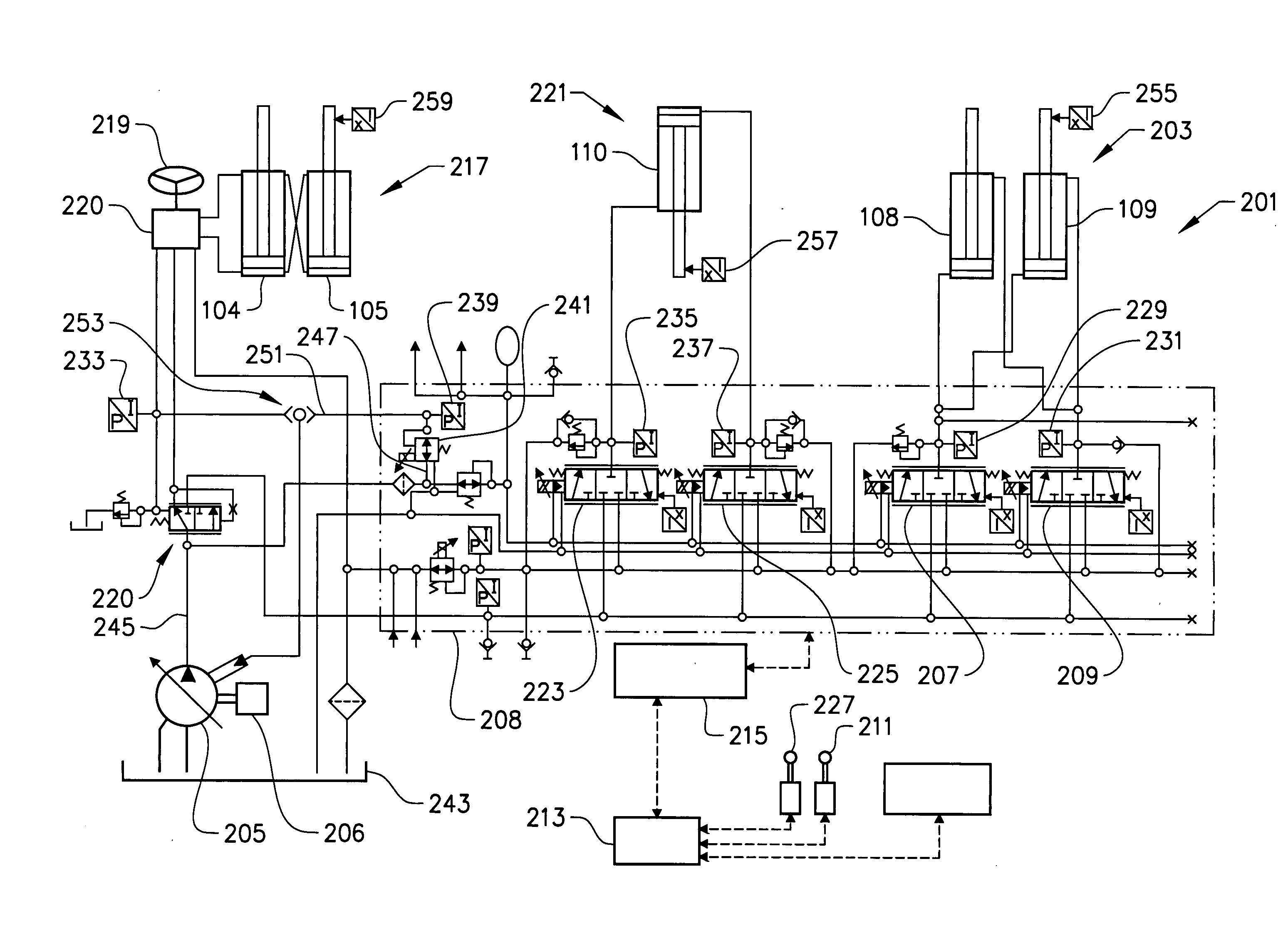
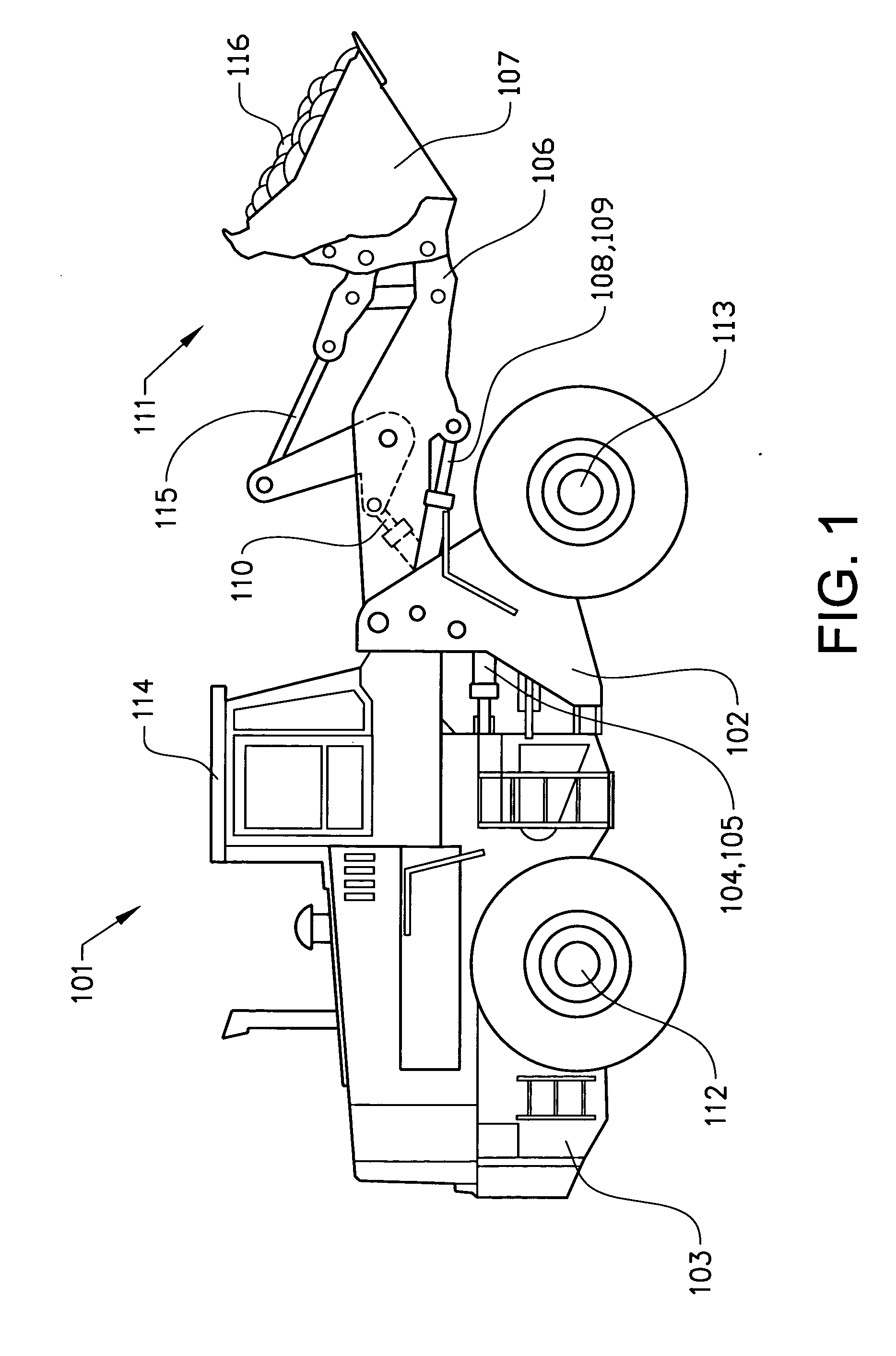
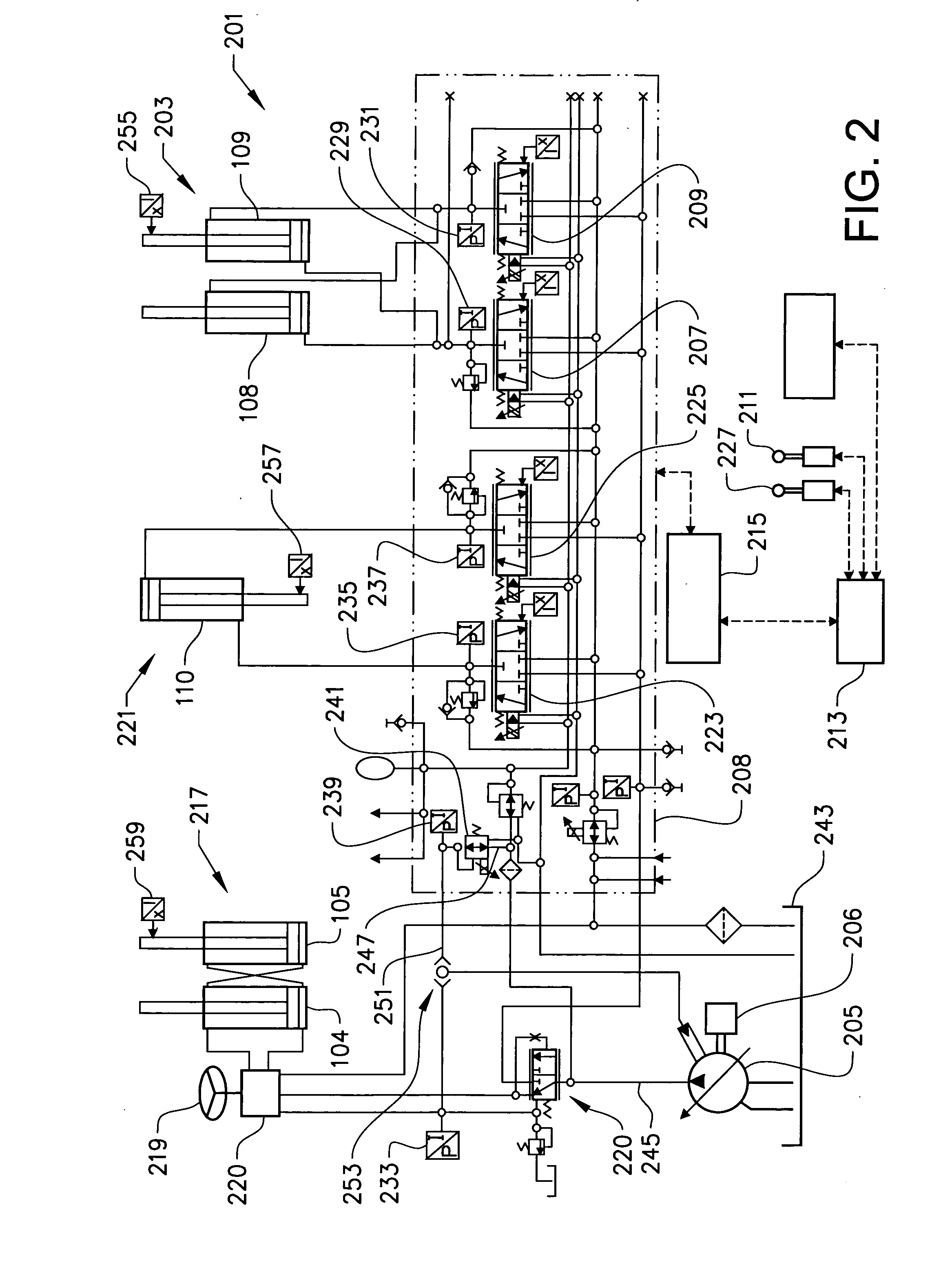
[0028]FIG. 1 shows a side view of a wheel loader 101. The wheel loader 101 comprises a front vehicle section 102 and a rear vehicle section 103, said sections each comprising a frame and a pair of drive shafts 112, 113. The rear vehicle section 103 comprises a operator's cab 114. The vehicle sections 102, 103 are connected to each other in such a way that they can be pivoted relative to each other about a vertical axis by means of two hydraulic cylinders 104, 105 which are connected to the two sections. Accordingly, the hydraulic cylinders 104, 105 are disposed on different sides of a centre line in the longitudinal direction of the vehicle for steering, or turning the wheel loader 101.

[0029]The wheel loader 101 comprises an equipment 111 for handling objects or material. The equipment 111 comprises a load-arm unit 106 and an implement 107 in the form of a bucket which is fitted on the load-arm unit. Here, the bucket 107 is filled with material 116. A first end of the load-arm unit ...


PUM


Abstract

A load sensing system includes a first assembly of actuators for controlling a first hydraulic function, a pump adapted to supply the actuators with pressurized hydraulic fluid, an electrically controlled valve adapted to control the output pressure of the pump via a hydraulic signal, a first pressure sensor for detecting a load pressure of the first actuator assembly, and a control unit adapted to receive a signal with information about the load pressure detected by the first pressure sensor and to generate a control signal, corresponding to the detected load pressure, to the electrically controlled valve.

Description

BACKGROUND AND SUMMARY[0001]The present invention relates to a load sensing system, comprising a first assembly of actuators for controlling a first hydraulic function, a pump adapted to supply said actuators with pressurized hydraulic fluid, and an electrically controlled valve adapted to control the output pressure of the pump via a hydraulic signal. In particular, the invention relates to a working machine comprising the system. A working machine in the form of a wheel loader has several different work functions which are hydraulically controlled, such as lifting and tilting of an implement and steering of the machine. As a rule, the actuators are constituted of linear motors in the form of hydraulic cylinders. The invention further relates to a method for controlling a hydraulic function.[0002]Below, the invention will be described in connection with the operation of a wheel loader. This is a preferred, but by no means limiting application of the invention. The invention can for...

Claims


Application Information

Patent Timeline
IPC IPC(8): F15B13/00
CPCE02F9/2228F15B2211/6346E02F9/2296F15B11/162F15B11/165F15B2211/20523F15B2211/20546F15B2211/253F15B2211/30565F15B2211/3144F15B2211/61F15B2211/6309F15B2211/6313F15B2211/6316F15B2211/6336E02F9/2235
Inventor VIGHOLM, BOEKVALL, ANDREAS
Owner VOLVO CONSTR EQUIP
Why Eureka
Try Eureka