
Solar light tracking sensor direction setting/measuring/re-adjusting method and solar light collecting device

a solar light tracking and direction setting technology, applied in lighting and heating equipment, pv power plants, instruments, etc., can solve the problems of difficult to accurately set the solar light tracking sensor b>12/b> to the sensor attaching position, and the cost of heliostats is not high, so as to avoid interference, avoid the effect of reducing the area of heliostats, and easy adjustment of the installation position of solar light tracking sensors

Inactive Publication Date: 2010-09-30
MITSUI ENG & SHIPBUILD CO LTD
View PDF8 Cites 16 Cited by
  • Summary
  • Abstract
  • Description
  • Claims
  • Application Information

AI Technical Summary

Benefits of technology

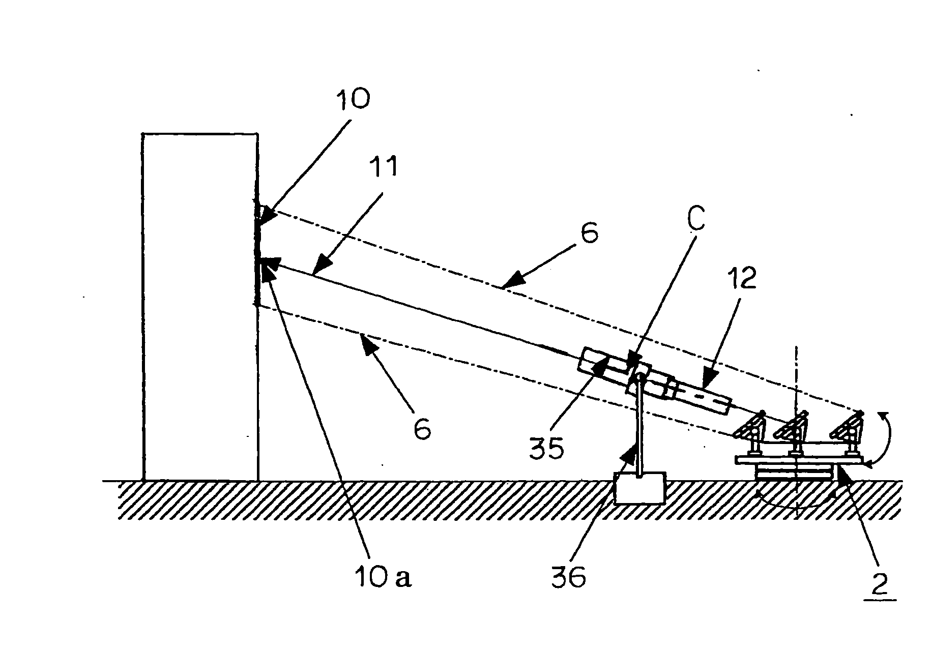
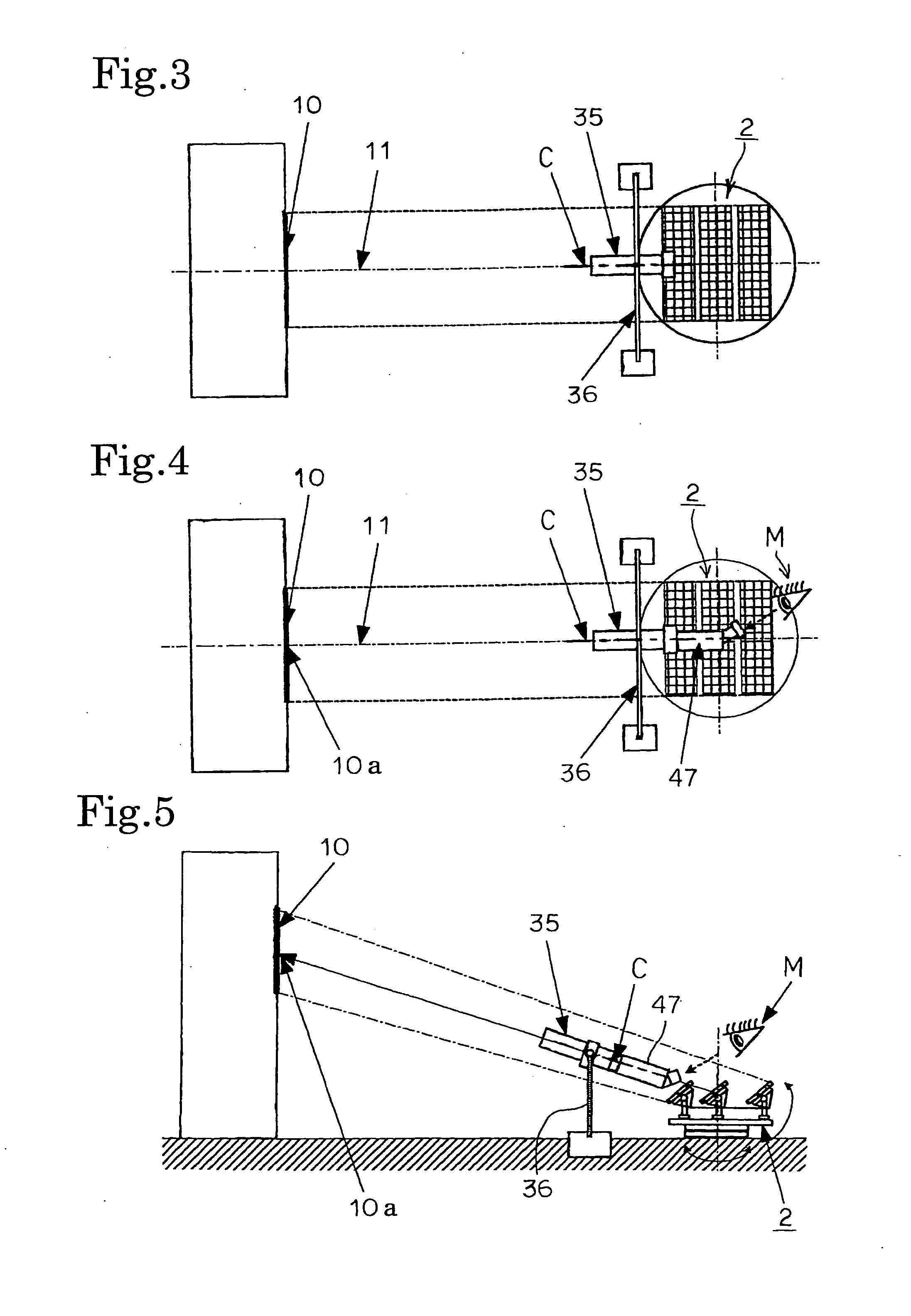
[0025]Since the invention according to claim 1 comprises the steps of, installing a solar light tracking sensor on an optical axis of reflected light collected by a heliostat, installing a solar light tracking guide on said optical axis to automatically control posture of the heliostat by the solar light tracking sensor, attaching an optical telescope to the rear end part of the solar light tracking guide so as to be aligned with a guide axis of the solar light tracking guide, adjusting the posture of said solar light tracking guide so that a cross provided in a field of view of the optical telescope agrees with the center of a light collection target position and fixing said solar light tracking guide to an installation base, and removing the optical telescope from the solar light tracking guide and attaching the solar light tracking sensor to the rear end part of the solar light tracking guide so as to be aligned with the guide axis of the solar light tracking guide, it is not necessary to mount the solar light tracking guide on the optical axis by using a transit or the like as in the conventional manner, and it is possible to install the solar light tracking sensor on the optical axis with ease and a high degree of accuracy compared with the conventional way.
[0026]Since the invention according to claim 2 comprises the steps of, installing a solar light tracking sensor on an optical axis of reflected light collected by a heliostat, attaching a laser light oscillator to the front end part of the solar light tracking guide to which said solar light tracking sensor is attached so as to be aligned with a guide axis of the solar light tracking guide, to automatically control posture of the heliostat by the solar light tracking sensor when a solar light tracking sensor optical axis displacement over time occurs, marking a light collection target position by oscillating laser light with the laser light oscillator, and measuring an amount of displacement of the marking point from said optical axis, it is possible to measure the solar light tracking sensor optical axis displacement with ease and a high degree of accuracy without requiring a large amount of labor.
[0027]Since the invention according to claim 3 comprises the steps of, installing a solar light tracking sensor on an optical axis of reflected light collected by a heliostat, attaching a laser light oscillator to the front end part of the solar light tracking guide to which said solar light tracking sensor is attached so as to be aligned with a guide axis of the solar light tracking guide, to automatically control posture of the heliostat by the solar light tracking sensor when a solar light tracking sensor optical axis displacement over time occurs, marking a light collection target position by oscillating laser light with the laser light oscillator, and re-adjusting posture of said solar light tracking guide so that the marking point agrees with the center of said light collection target position, it is possible to re-adjust the solar light tracking sensor optical axis displacement over time with ease and a high degree of accuracy.
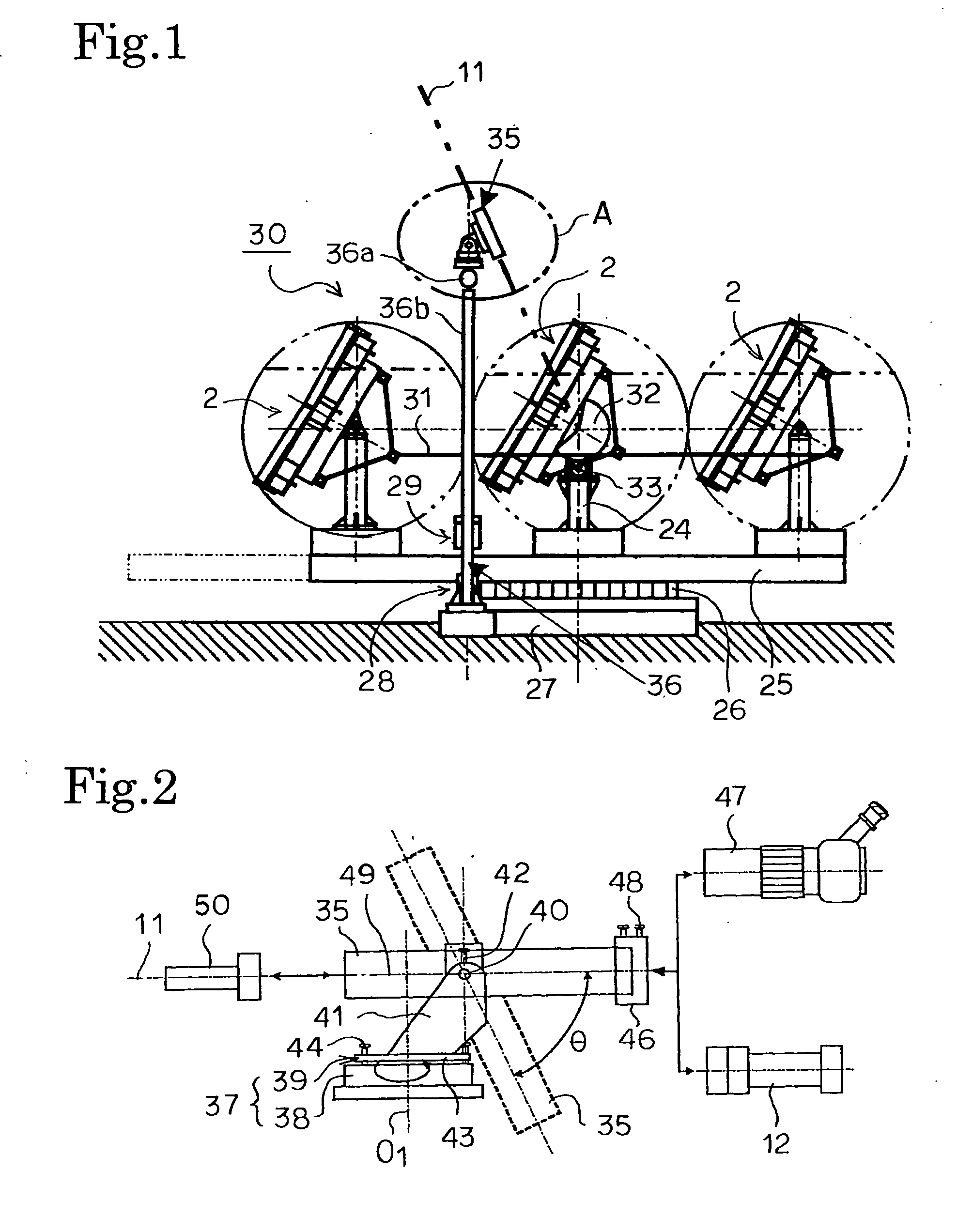
[0028]Since the invention according to claim 4 is the one having a solar light tracking sensor installed on an optical axis of reflected light collected by a heliostat, and automatically controlling posture of the heliostat by the solar light tracking sensor, wherein a solar light tracking sensor installation mount for supporting said solar light tracking sensor is separated from a heliostat installation base and is installed outside of the heliostat installation base system, it is possible to avoid interference between the heliostat and the solar light tracking sensor installation mount, so that it is possible to avoid a reduction of the area of heliostat resulted from the solar light tracking sensor installation position. In addition, according to this invention, since the solar light tracking sensor installation mount is separated from the heliostat installation base, it is possible to easily adjust the solar light tracking sensor installation position.

Problems solved by technology

Although the trough type light collecting device has a design easy to be changed in accordance with the size of installation site, an amount of collected solar light is smaller than that of the tower type light collecting device, and hence the temperature is not so high that high efficiency cannot be expected.
Therefore, although the tower type light collecting device can generate electric power with high efficiency compared with other light collecting devices, the tower type light collecting device is not profitable unless it is large-scale.
As described above, in the conventional center installation method, the sensor attaching position is determined by measurement, however it is difficult to accurately set the solar light tracking sensor 12 to the sensor attaching position on which the “marks” are attached by measurement.
Even when the solar light tracking sensor is accurately attached by the above method, deviation (displacement) occurs in the target optical axis due to external disturbances (for example, wind, heat, vibration, and the like), and, as a result, deviation occurs in the light collection performance, or the light collection performance deteriorates.
In addition, to measure the amount of the displacement, a lot of works are required.

Method used


Image

  • Solar light tracking sensor direction setting/measuring/re-adjusting method and solar light collecting device
  • Solar light tracking sensor direction setting/measuring/re-adjusting method and solar light collecting device
  • Solar light tracking sensor direction setting/measuring/re-adjusting method and solar light collecting device

Examples


Embodiment Construction

[0050]Hereinafter, an embodiment of the present invention will be described with reference to the drawings. Although FIG. 1 shows flat type heliostats, the embodiment can also be applied to T-bone type heliostats.

[0051]As shown in FIG. 1, in a solar light collecting device 30 related to the present invention, a plurality of heliostats for collecting solar light is set on a rotating table 25 via heliostat bases 24. Although, a mirror attached to the heliostat 2 is essentially desired to be manufactured to have a three-dimensional curved surface with conic curve, in fact, small mirrors (facets) are combined to form a virtual conic curve, because of the high manufacturing cost and difficulty in maintaining accuracy of the three-dimensional curved surface with conic curve.

[0052]The rotating table 25 is rotated clockwise or counterclockwise along with a large gearwheel 26 provided on the bottom surface of the rotating table 25. The large gear wheel 26 fixed to the bottom surface of the r...


PUM


Abstract

The direction of a solar light tracking sensor is set easily with high accuracy. A solar light tracking guide (35) is installed on the optical axis (11) of the reflected light collected by a heliostat (2). An optical telescope (47) is so attached to the rear end part of the guide (35) as to be aligned with the guide axis (C) of the guide (35). The posture of the solar light tracking guide (35) is so adjusted that a cross provided in the field of view of the telescope (47) agrees with the center (10a) of the light collection target position and fixed to the base (38). Then, a solar light tracking sensor (12) is fastened to the rear end part of the guide (35) in place of the optical telescope (47).

Description

TECHNICAL FIELD[0001]The present invention relates to a direction setting method, an optical axis displacement measuring method, and a re-adjusting method of a solar light tracking sensor, and to a solar light collecting device.BACKGROUND ART[0002]As a solar light collecting device applied to a solar thermal power generation device, conventionally, three types of light collecting devices are known: a trough type (distributed type) light collecting device; a tower type (light collecting type) light collecting device; and a dish type light collecting device.[0003]The trough type light collecting device collects solar light by a parabolic curved mirror and heats a pipe (heat collecting pipe) filled with liquid (heat medium). Although the trough type light collecting device has a design easy to be changed in accordance with the size of installation site, an amount of collected solar light is smaller than that of the tower type light collecting device, and hence the temperature is not so...

Claims


Application Information

Patent Timeline
IPC IPC(8): H01L31/042F24J2/38F24S50/20
CPCY02E10/47F24J2/10F24J2/1047F24J2002/385F24J2/541F24J2/542F24J2/38F24S23/80F24S50/20F24S23/70F24S30/425F24S30/452F24S2050/25G01S3/7861G02B23/16
Inventor EZAWA, KAZUAKIOKU, KOUNOSUKEFUJIWARA, KAZUMASAKAWAGUCHI, TAKASHI
Owner MITSUI ENG & SHIPBUILD CO LTD
Learn More