Supercharge Your Innovation With Domain-Expert AI Agents!

Apparatus and method for forming a clay slab

a technology of clay slabs and apparatus, applied in the field of apparatus and methods for forming clay slabs, can solve the problems of substantial floor space, limited use of most pottery, sculpture and artwork workshops, and limited use of most clay-making, sculpture and artwork

Active Publication Date: 2010-09-30
BELLAR DAVID
View PDF11 Cites 0 Cited by
  • Summary
  • Abstract
  • Description
  • Claims
  • Application Information

AI Technical Summary

Benefits of technology

[0007]The aforementioned needs, objectives and advantages, as well as others that will be readily apparent to those of ordinary skill in the art, are provided by a

Problems solved by technology

Regardless, all known slab rollers have the disadvantage that the slab roller is oriented in a horizontal direction so as to work the prepared clay and form the clay slab on a horizontal surface, such as a tabletop, counter or elongated workspace of the slab roller.
However, a slab roller oriented in a horizontal direction occupies a substantial amount of floor space, which in most pottery, sculpture and artwork workshops is limited.
Although some slab rollers are configured to be moved from a horizontal orientation for working to a vertical orientation for storage, such slab rollers still require a substantial amount of floor space while forming the clay slab and furthermore require an additional expenditure of manpower and time to convert the slab roller from the horizontal orientation to the vertical orientation.
A horizontally oriented slab roller also provides no mechanical advantage to the process of molding the prepared clay into a relatively flat clay slab having a generally uniform thickness.
In particular, feeding the prepared clay into the slab roller is not assisted by gravity.
To the contrary, gravity works against the molding process with a conventional slab roller since the clay slab tends to bunch up as the weight of the prepared clay exiting the rollers experiences increasing friction with the horizontal table.
Another disadvantage of the known slab rollers is that one or more rollers are driven by a complex arrangement of cranks, gears, cables or the like, directly over the prepared clay.
The use of a driven roller to drive the clay often results in the clay slab having an undesirable grain direction and / or an uneven or rough exterior surface.
A predetermined grain direction is undesirable because non-isotropic stress patterns can develop in the work piece during firing and subsequent quenching, which may cause the finished piece to shift or warp.
A clay slab having an uneven or rough exterior surface can result in the finished piece of clay pottery, sculpture or artwork having an undesirable exterior surface.
Other shortcomings and disadvantages inherent in slab rollers oriented in a horizontal direction include the tendency for complicated gearboxes that transfer force from the crank to the rollers to wear out, fail or require frequent adjustment.
In addition, the known slab rollers include inferior adjustment mechanisms for adjusting the distance between the driven rollers, and consequently, the thickness of the clay slab.
Adjustment mechanisms for existing slab rollers are not synchronized, and thus, do not always produce a clay slab having a generally uniform thickness.
Furthermore, the panels of flexible material (e.g. canvas fabric) utilized with most existing slab rollers are not integrally formed or attached to one another in any manner.
Accordingly, the panels must first be located, arranged on the slab roller and aligned, resulting in a significant expenditure of set-up time before the clay slab can be formed.
If the driven rollers are not adjusted accurately, or the loose canvas fabric is not positioned properly and carefully aligned, the prepared clay may tend to wander off to one side, thereby requiring the clay slab to be re-formed and resulting in a further expenditure of time.
Accordingly, there exists an unresolved need for an apparatus and method for forming a clay slab that overcomes the disadvantages of known slab rollers and associated methods.

Method used


Image

  • Apparatus and method for forming a clay slab
  • Apparatus and method for forming a clay slab
  • Apparatus and method for forming a clay slab

Examples


Embodiment Construction

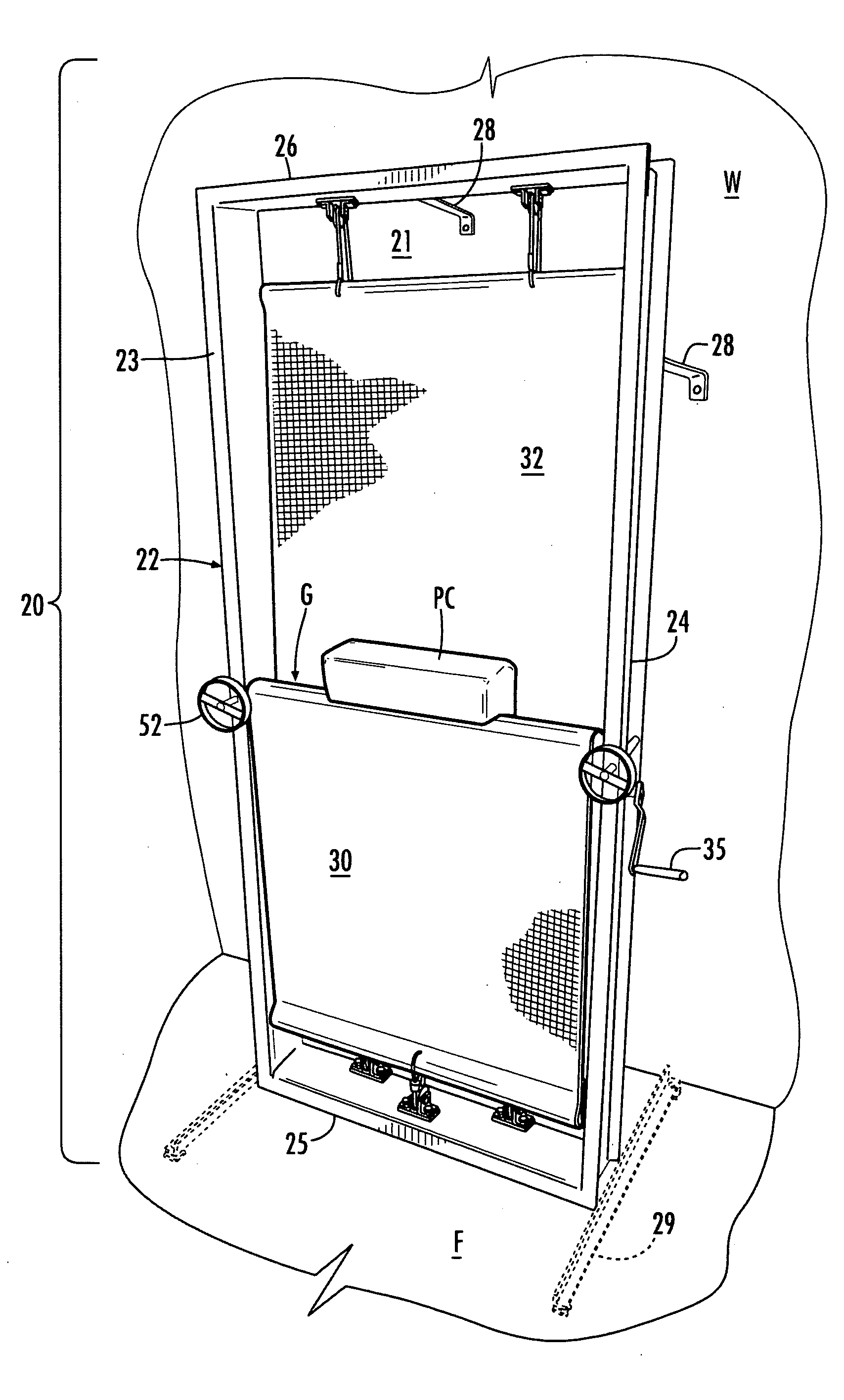
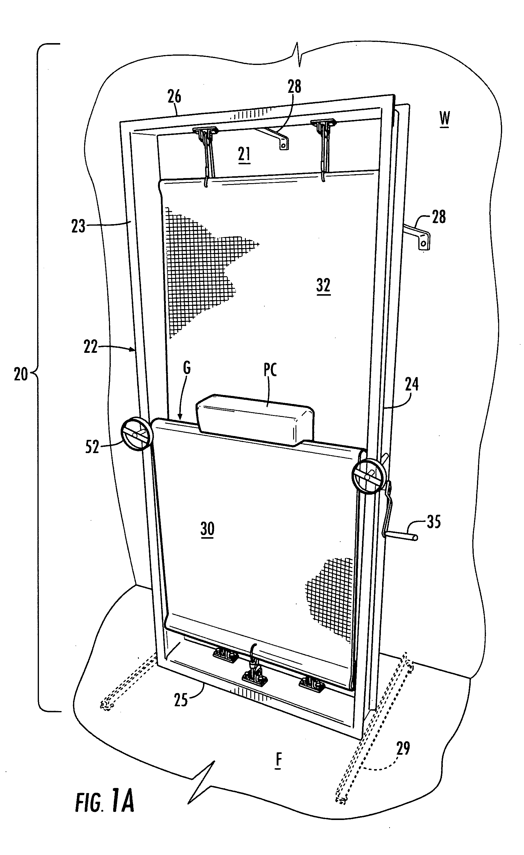
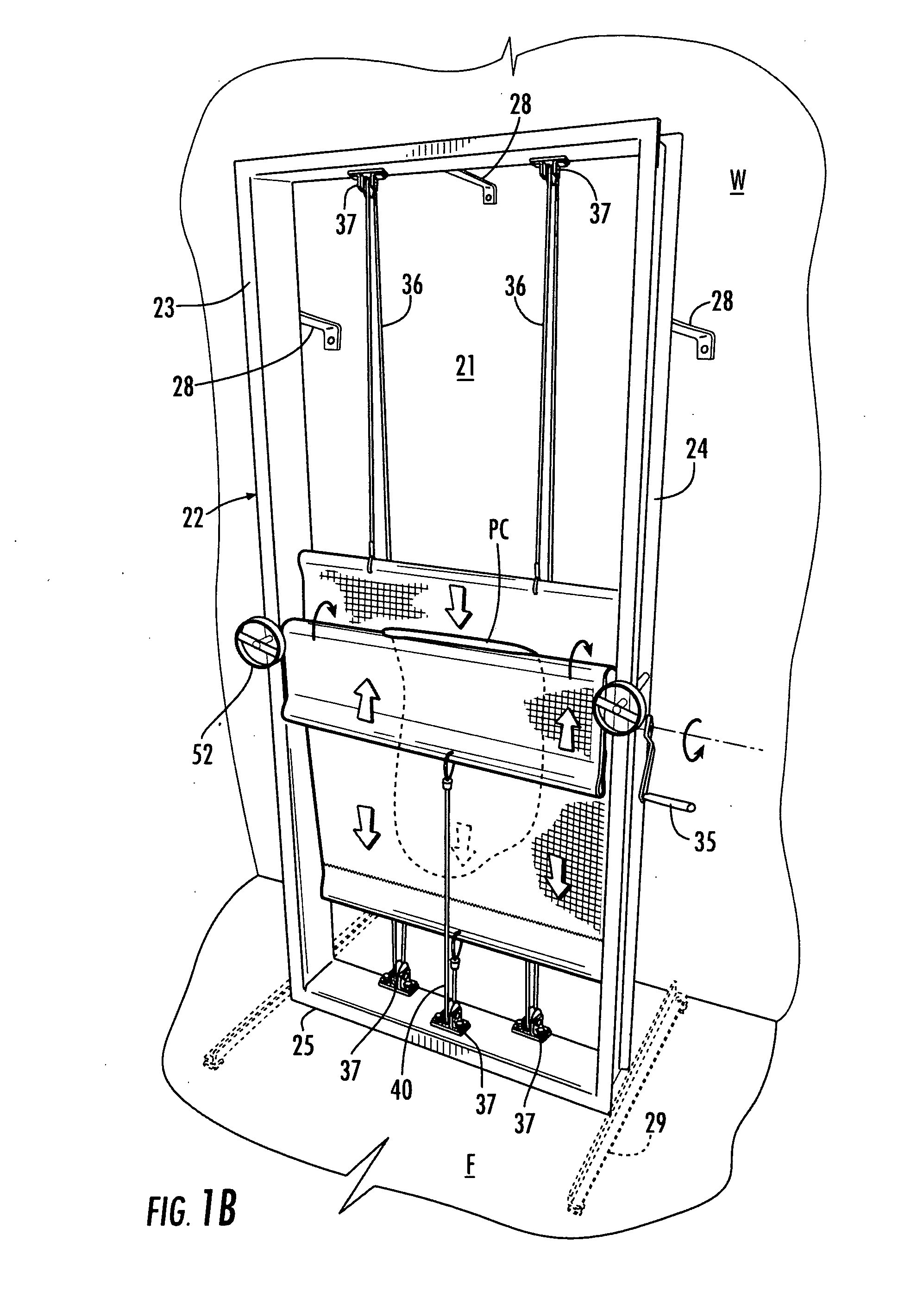
[0056]Referring now to the accompanying drawing figures in which identical reference numerals denote the same or similar elements throughout the various views, an apparatus for forming a clay slab according to the invention is shown. The apparatus, also referred to herein as the “slab roller” and indicated generally at 20, is operable for working prepared clay to form a relatively flat clay slab having a generally uniform thickness of the type used for making clay pottery, sculpture and artwork. The apparatus comprises a frame 22 oriented in a vertical direction relative to a horizontal floor F and a vertical wall W (or other support) of a work space in, for example, a pottery shop or art studio. As shown, the frame 22 includes a pair of spaced apart side frame members 23, 24 separated by a lower frame member 25 adjacent the floor F and an upper frame member 26 vertically spaced from the lower frame member. Each of the frame members 23, 24, 25, 26 is preferably made of metal and for...


PUM

PropertyMeasurementUnit
Lengthaaaaaaaaaa
Thicknessaaaaaaaaaa
Pressureaaaaaaaaaa

Abstract

An apparatus and method for forming a clay slab includes a frame, a front panel supported on the frame and a rear panel supported on the frame. An outer cable is attached to the rear panel at one end and to the rear panel and to the front panel at another end. A rotatable drive axle is configured to simultaneously wind and unwind the outer cable and thereby move the front panel and the rear panel from an initial position to an intermediate position to draw a block of prepared clay into a gap defined by the front panel and the rear panel. The drive axle is further configured to simultaneously wind and unwind the outer cable in the opposite direction and thereby move the front panel and the rear panel from the intermediate position back to the initial position to remove the clay slab from the slab roller.

Description

BACKGROUND OF THE INVENTION[0001]The invention relates to an apparatus and method for forming a clay slab. More particularly, the invention is a slab roller and an associated method for working prepared clay into a relatively flat clay slab having a generally uniform thickness of the type used in making clay pottery, sculpture and artwork. In a preferred embodiment, the invention is a slab roller that is oriented in a vertical direction. In another preferred embodiment, the invention is a slab roller configured to draw prepared clay between opposed panels of a flexible material to form a relatively flat clay slab having a generally uniform thickness.[0002]Clay used in making pottery, sculpture and artwork is typically cut from a large block of prepared clay and worked (also referred to as “molded”) into a relatively flat clay slab having a generally uniform thickness. Various equipment and techniques are employed for working the clay depending on the desired size, shape and uniformi...

Claims


Application Information

Patent Timeline
IPC IPC(8): B29C59/02B29C43/00
CPCB28B3/12B30B5/04B30B3/04
Inventor BELLAR, DAVID
Owner BELLAR DAVID
Features
  • R&D
  • Intellectual Property
  • Life Sciences
  • Materials
  • Tech Scout
  • Unparalleled Data Quality
  • Higher Quality Content
  • 60% Fewer Hallucinations
Learn More