Method and circuit for low power voltage reference and bias current generator

a low power voltage and bias current technology, applied in the field of voltage references, can solve the problems of increasing cost and contributing to the total noise of the resulting ptat voltag

Active Publication Date: 2010-09-30
ANALOG DEVICES INC
View PDF7 Cites 15 Cited by
  • Summary
  • Abstract
  • Description
  • Claims
  • Application Information

AI Technical Summary

Problems solved by technology

In some applications, for example low power applications, the resistor 120 may be large and even dominate the silicon die area, there

Method used


Image

  • Method and circuit for low power voltage reference and bias current generator
  • Method and circuit for low power voltage reference and bias current generator
  • Method and circuit for low power voltage reference and bias current generator

Examples


Embodiment Construction

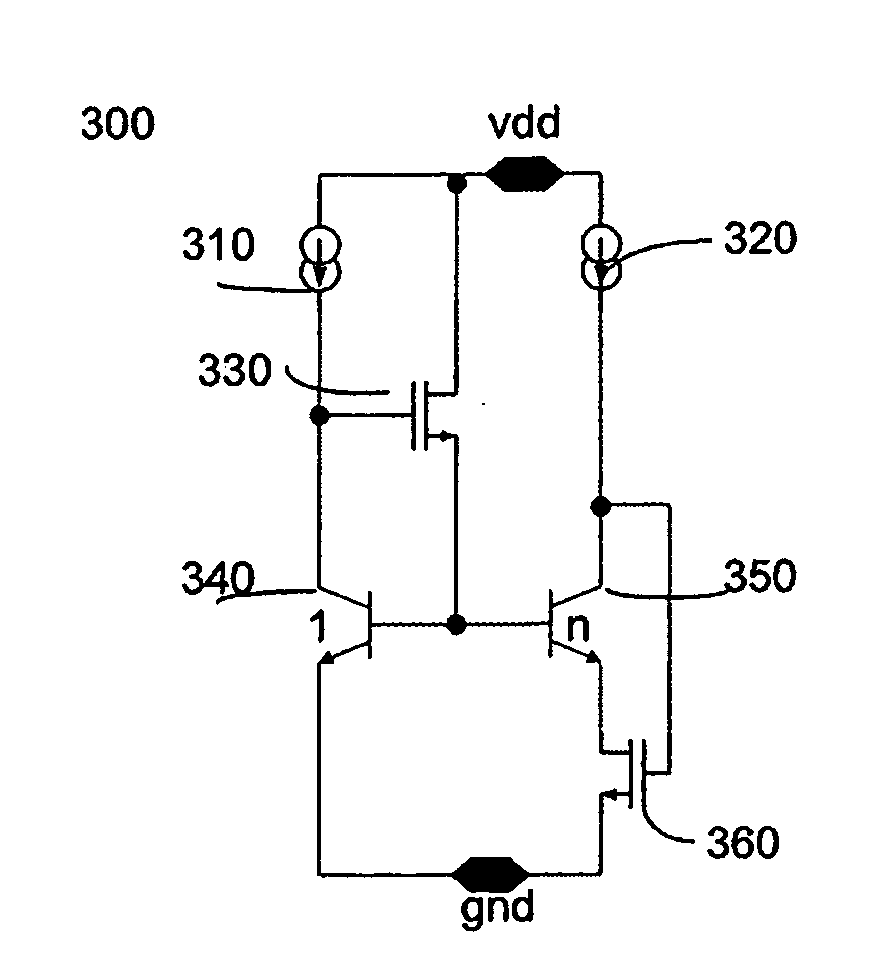
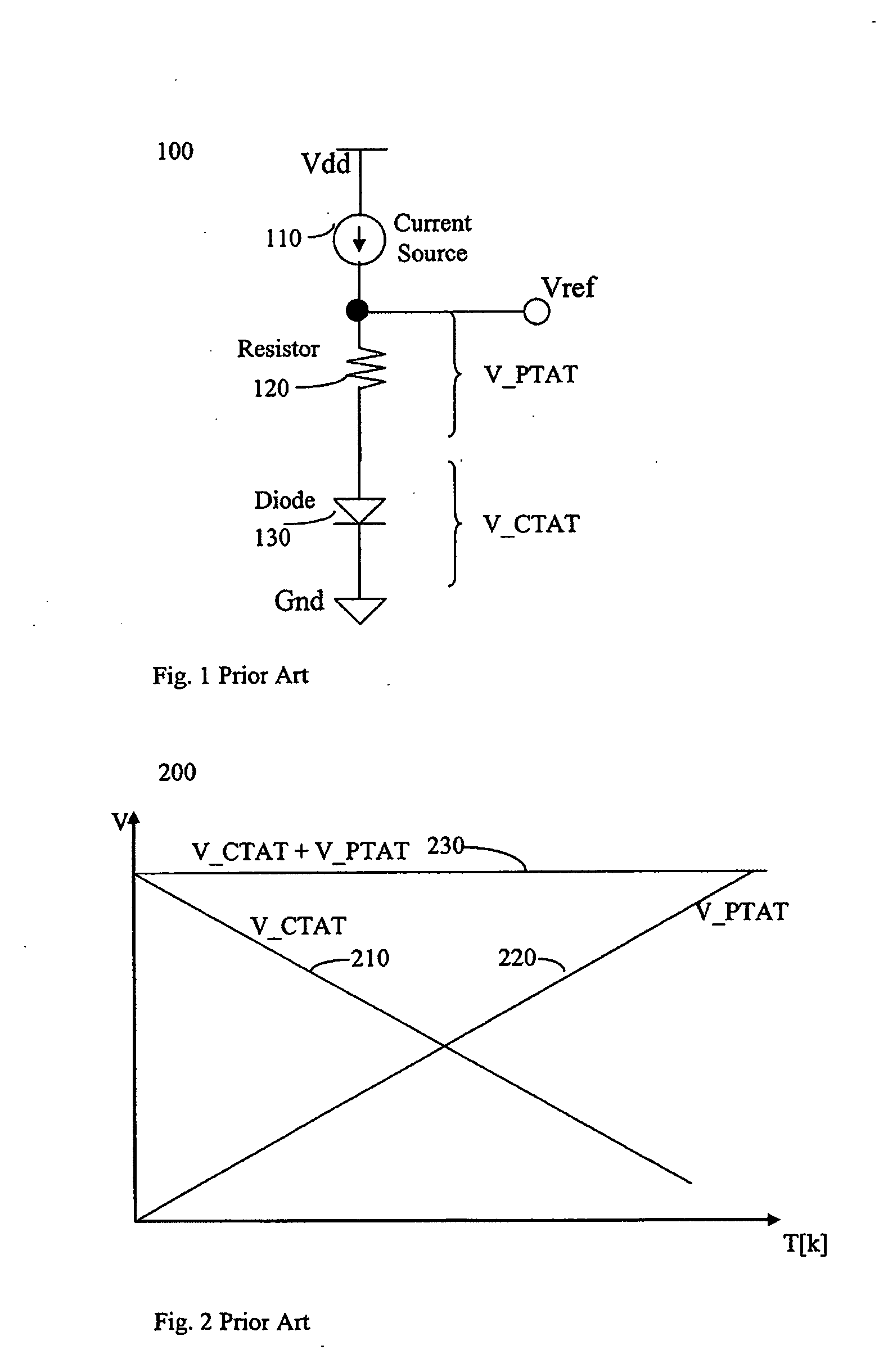
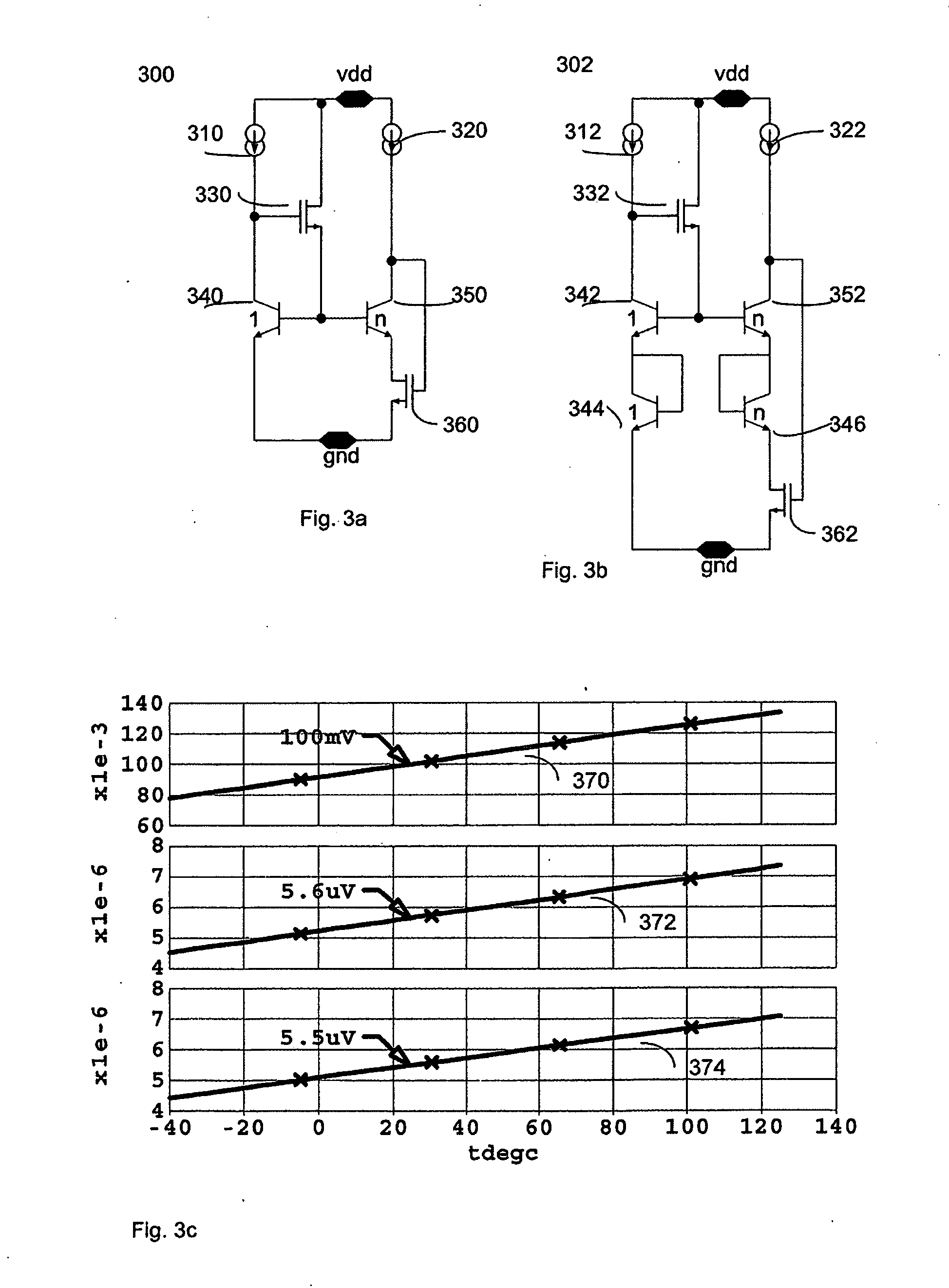
[0023]A system and method are provided for a PTAT cell with no resistors which can operate at low power, has less sensitivity to process variation, occupies less silicon area, and has low noise. In another aspect of the invention, a system and method are provided to scale up the reference voltage and current. In yet another aspect of the present invention, a system and method are provided for a PTAT component to be fine-tuned.

[0024]The resistorless PTAT cell of FIG. 3a is an embodiment of an aspect of the present invention. Circuit 300 includes a first set of circuit elements arranged to provide a complimentary to absolute temperature (CTAT) voltage. For example, the first set of circuit elements may comprise transistors 330 and 340, which are supplied by current source 310. Transistor 330 may be, for example, an NMOS. A second set of circuit elements are arranged to provide a proportional to absolute temperature (PTAT) voltage or current. For example, the second set of circuit elem...


PUM


Abstract

A system and method are provided for a PTAT cell with no resistors which can operate at low power, has less sensitivity to process variation, occupies less silicon area, and has low noise. Further, a system and method are provided to scale up the reference voltage and current through a cascade of unit cells. Still further, a system and method are provided for PTAT component to be fine-tuned, advantageously providing less process variability and less temperature sensitivity.

Description

COPYRIGHT AND LEGAL NOTICES[0001]A portion of the disclosure of this patent document contains material which is subject to copyright protection. The copyright owner has no objection to the facsimile reproduction by anyone of the patent document or the patent disclosure, as it appears in the Patent and Trademark Office patent files or records, but otherwise reserves all copyrights whatsoever.FIELD OF THE INVENTION[0002]The present invention relates generally to voltage references and in particular to voltage references implemented using bandgap circuitry. The present invention more particularly relates to a circuit and method which provides a Voltage Proportional to Absolute Temperature (PTAT) voltage which can be scaled and tuned.BACKGROUND INFORMATION[0003]A conventional bandgap voltage reference circuit is based on the addition of two voltage components having opposite and balanced temperature slopes.[0004]FIG. 1 illustrates a symbolic representation of a conventional bandgap refe...

Claims


Application Information

Patent Timeline
IPC IPC(8): G05F3/16
CPCY10S323/908G05F3/30
Inventor MARINCA, STEFAN
Owner ANALOG DEVICES INC
Why Eureka
Try Eureka