Wireless Clamp-on Current Probe

a clamp-on current and probe technology, applied in the direction of wireless architecture, instruments, base element modifications, etc., can solve the problems of lack of electrical isolation from the circuit under test, lack of connection to external instruments, and heat generation

Inactive Publication Date: 2010-09-30
OECO
View PDF7 Cites 27 Cited by
  • Summary
  • Abstract
  • Description
  • Claims
  • Application Information

AI Technical Summary

Benefits of technology

[0008]The wireless clamp-on current probe of the present invention combines a clamp-on current probe with an embedded system which includes an RF transceiver to enable stationary test equipment to connect to current probes, without regard to cabling issues such as size, physical wear of cables, weight, cost, electrical noise, losses and other issues related to physical connections. The apparatus and method of the present invention also permit the use of current probes in environments and situations not previously possible.

Problems solved by technology

The drawbacks of using shunt resistors include but are not limited to inherent power losses, the need to interrupt the circuit path to insert the meter in-line, heat generation, and the absence of electrical isolation from the circuit under test.
Some clamp-on current probes are totally self contained and have visual indication of the magnitude of the current being measured, but do not have a means of connecting to external instruments.
Unfortunately, there are certain circumstances in which the use of such a wired interface between a current probe and a test and measurement instrument, or a data collection instrument, may be undesirable, or even dangerous to the user.

Method used


Image

  • Wireless Clamp-on Current Probe
  • Wireless Clamp-on Current Probe
  • Wireless Clamp-on Current Probe

Examples


Embodiment Construction

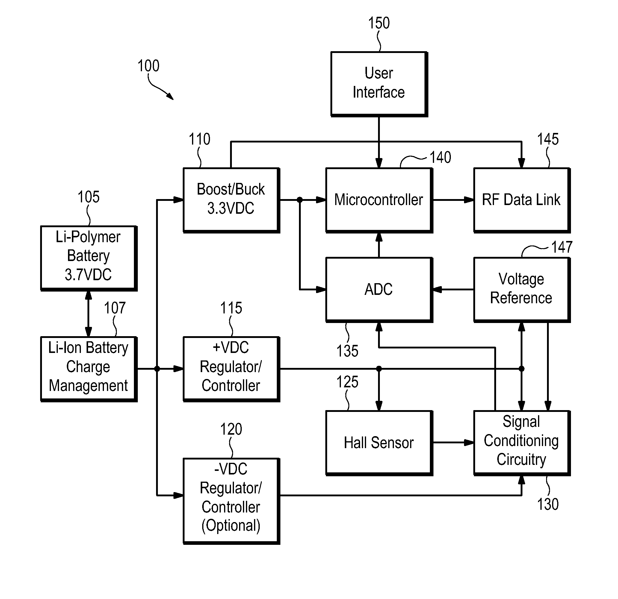
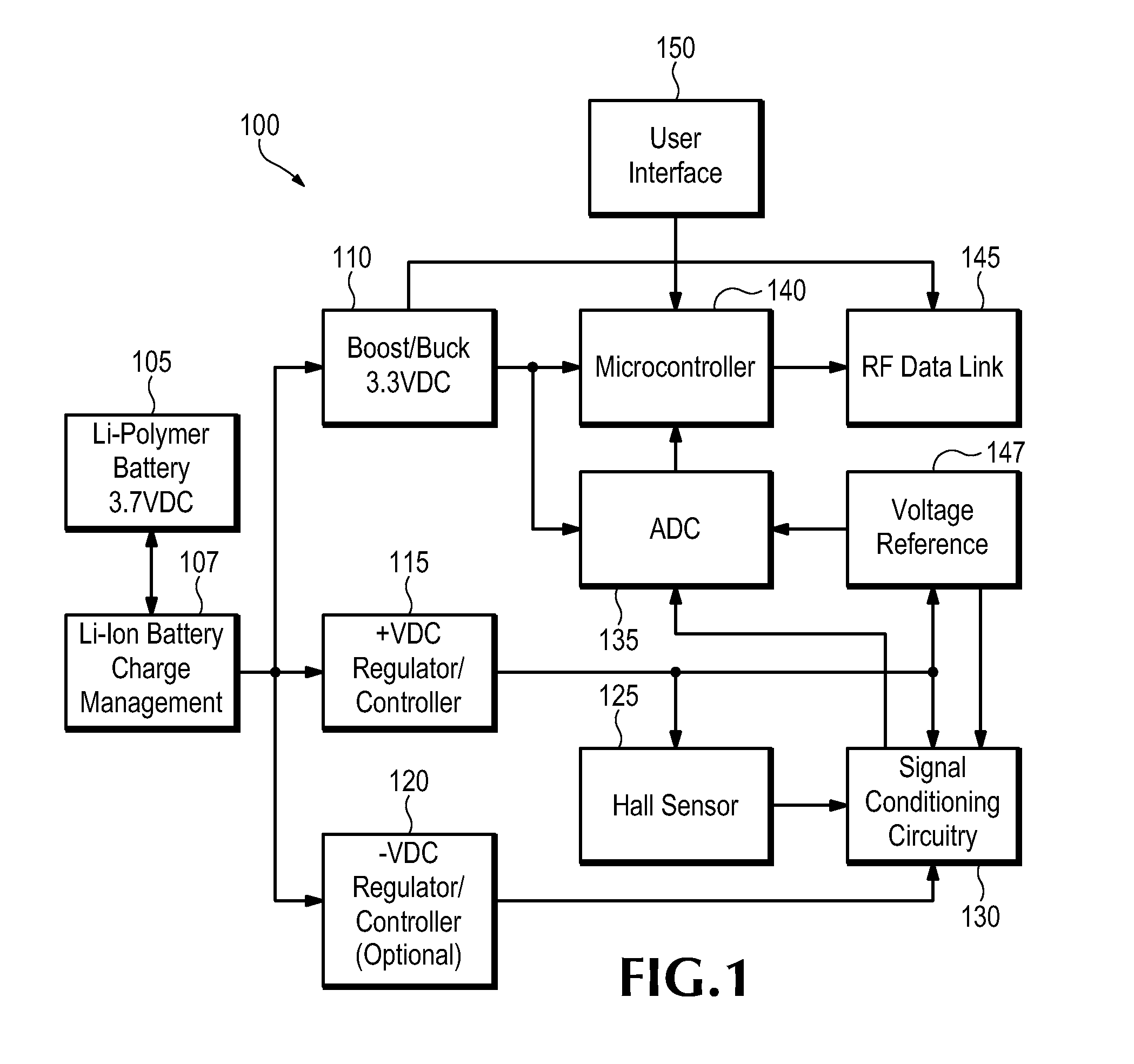
[0033]The apparatus and method of the present invention can be used to make noncontact current measurements of the current passing through a conductor without interrupting the electrical circuit being tested, and wirelessly transmit the measured data to a receiving unit. The apparatus of the present invention can be clamped onto a conductor to measure the current passing through it and wirelessly transmit the measured current value to a receiver unit. This information can be made available on demand or optionally logged.

[0034]The apparatus of the present invention may include a variety of elements arranged in different combinations depending on the use of the apparatus. Such elements that may be found in the apparatus of the present invention include, but are not limited to, voltage regulators, precision voltage references, radio transceivers, battery charge management controllers, lithium batteries, microcontrollers, nonvolatile memory, analog-to-digital converters, Hall Effect sen...


PUM


Abstract

A Wireless Clamp-on Current Probe and an embedded system which includes a digital RF transceiver allows for remote test and measurement equipment to receive data from a current probe without regard to cabling issues such as size, physical wear, weight, cost, electrical noise, losses and more. Such a current probe may be used in environments and situations not previously explored. The probe may be controlled and queried by wired serial communication means or by means of an integrated radio frequency (RF) transceiver. The RF transceiver may utilize a proprietary communication protocol or a standard wireless communication protocol such as ZigBee, Bluetooth or any of the IEEE communication standards.

Description

CROSS REFERENCE TO RELATED PATENT APPLICATIONS[0001]This application claims priority to U.S. Provisional Application Ser. No. 61 / 211,143 filed on Mar. 26, 2009, which is incorporated herein by reference in its entirety.FIELD OF THE INVENTION[0002]The invention relates generally to an apparatus and method for measuring the magnitude of an electrical current. In particular, the apparatus and the method of the present invention provide measurement of electrical current by a clamp-on current probe.BACKGROUND OF THE INVENTION[0003]Clamp-on current probes are used to make noncontact current measurements of the current passing through a conductor without interrupting the electrical circuit being tested. Other methods of measuring current passing through a conductor include the use of shunt resistors. The drawbacks of using shunt resistors include but are not limited to inherent power losses, the need to interrupt the circuit path to insert the meter in-line, heat generation, and the absenc...

Claims


Application Information

Patent Timeline
Patent Type & Authority Applications(United States)
IPC IPC(8): G01R31/02
CPCG01R1/04G01R1/06788G01R1/22G01R15/125H04Q2209/88G01R15/207H04Q9/00H04Q2209/43G01R15/202
Inventor CANTAVE, GUILFORD L.FRANCESCHINI, STEVEN M.
Owner OECO
Why Eureka
Try Eureka