Transformer

a transformer and transformer body technology, applied in the direction of transformer/inductance details, inductances, inductances with magnetic cores, etc., can solve the problems of increasing the size of the overall transformer, complex shape and structure of the insulating member, and not achieving the desired insulation performance. , to achieve the effect of reducing the size and simplifying the overall structure and assembly operation

Active Publication Date: 2010-09-30
NJ COMPONENTS CO LTD
View PDF17 Cites 8 Cited by
  • Summary
  • Abstract
  • Description
  • Claims
  • Application Information

AI Technical Summary

Benefits of technology

[0031]As a result, the primary coil or the secondary coil can be protected from the other members that otherwise interfere therewith, whereby the overall structure and assembling operation can further be simplified because it is not necessary to wind a separate protective tape or any other suitable component around the outer circumference of the coil.
[0032]Further, when a plurality of annular protrusions are formed at certain intervals in the axial direction around the outer circumference of the outer circumference sheath member, the insulation distance between the primary-side parts and the secondary-side parts is the length along the protrusions and recesses in the axial direction, whereby the insulation distance can be longer than the axial straight length of the outer circumference sheath member (specifically, longer by the number of protrusions×the height of each of the protrusions×2). Therefore, the configuration described above allows further size reduction and is preferable when a high voltage is inputted to the primary coil.

Problems solved by technology

In addition to the above, even if insulation is ensured between the primary and secondary coils in a high-voltage producing transformer of this type, a core that is disposed around the coils to form a closed magnetic path is not an insulator and, therefore, desired insulation performance is not obtained in the presence of the core.
In the transformer described in Patent Document 1, however, it is necessary to provide the insulating member not only between at least one of the core members and the through hole in the bobbin but also across the total length of the core member in order to achieve a desired advantageous effect, resulting in a problem of a complicated shape and structure of the insulating member, for example, when the core member is an E-shaped core.
Further, since the insulating member is provided between the core member and the through hole, the through hole in the bobbin needs to be larger than'a conventional size, resulting in an increased size of the overall transformer, which is disadvantageously against a recent demand for size reduction.

Method used


Image

  • Transformer
  • Transformer
  • Transformer

Examples


first embodiment

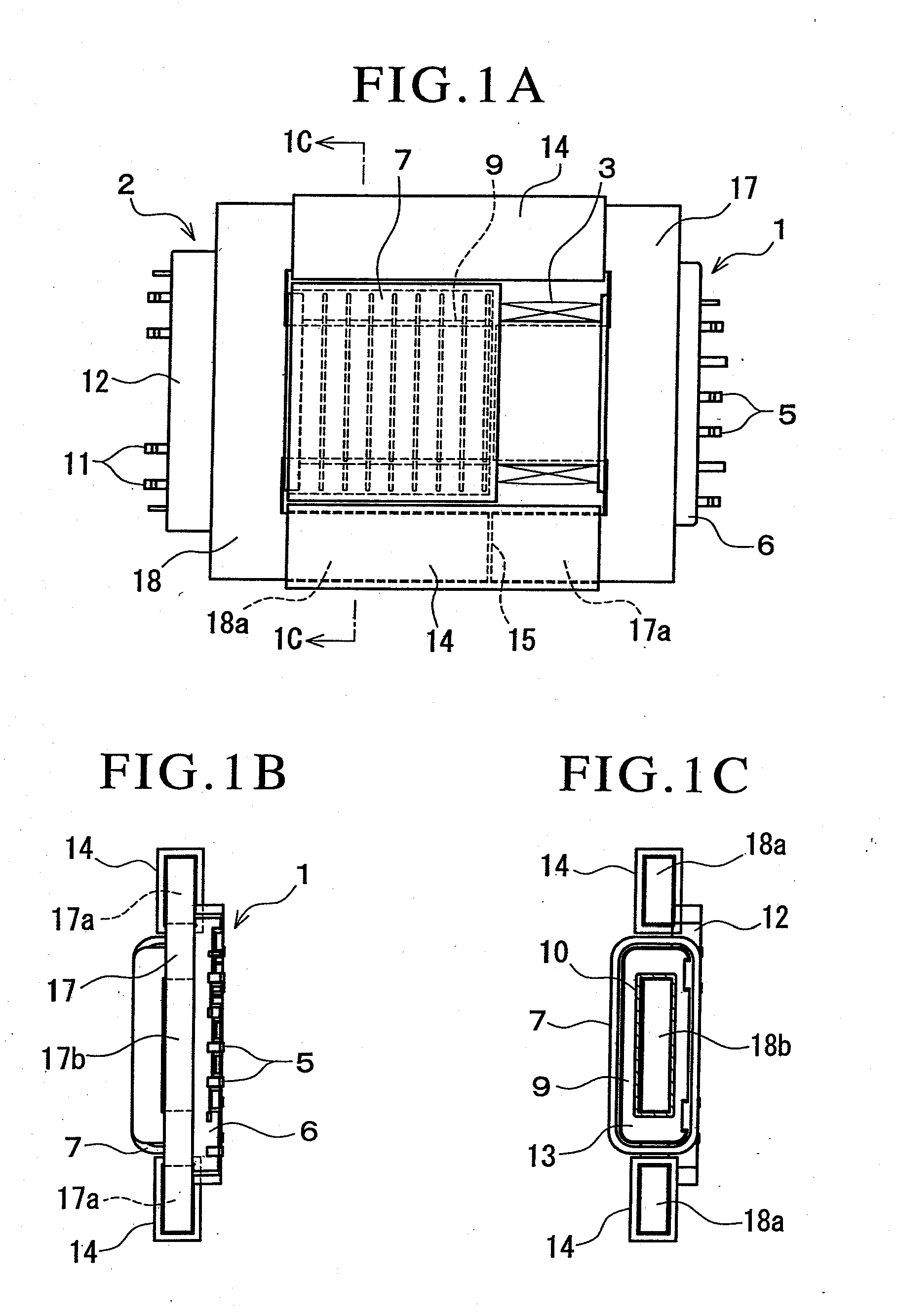
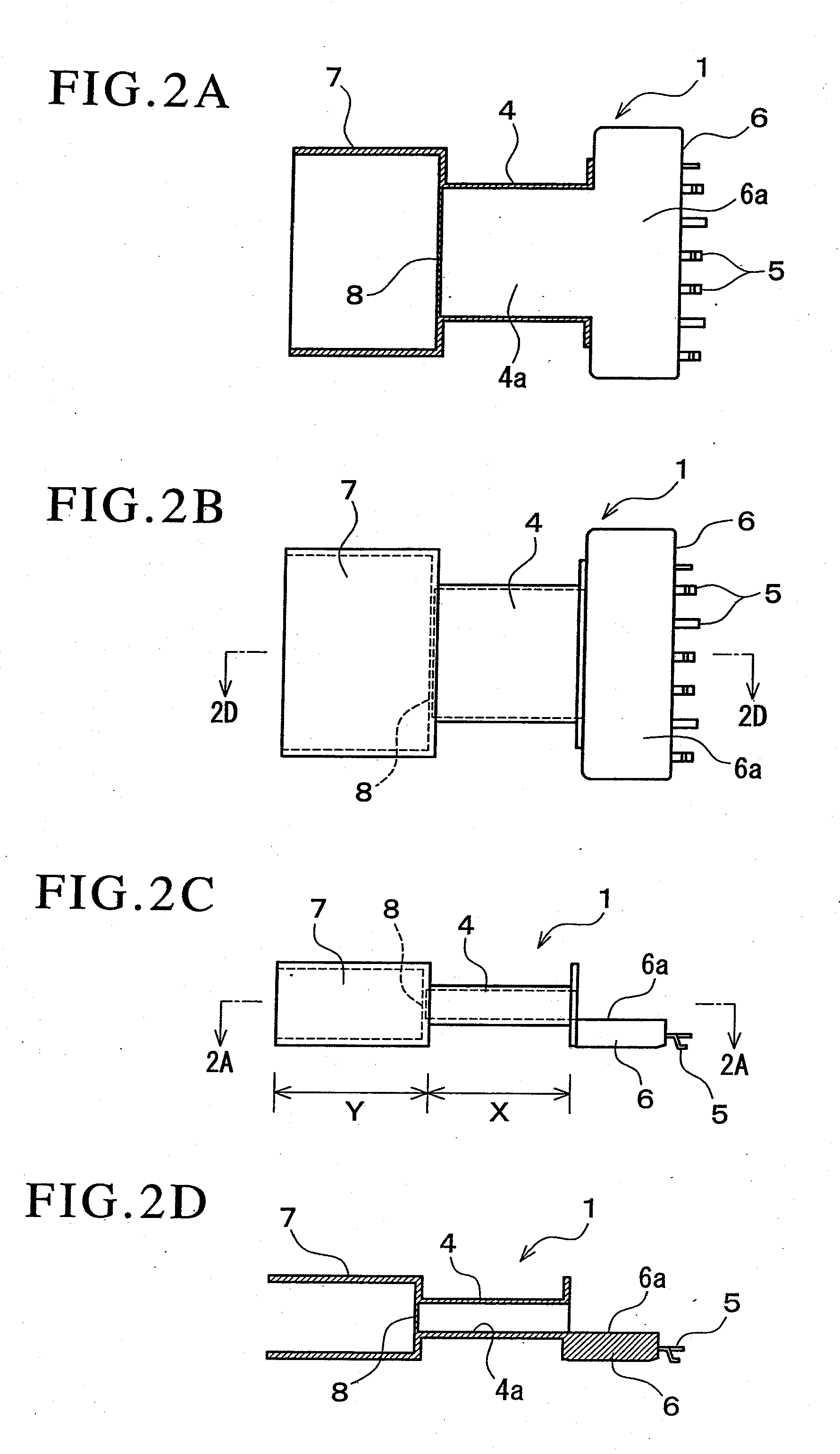
[0091]FIGS. 1A to 7B show a first embodiment and a variation thereof in which a transformer according to the present invention is used as an inverter transformer for causing a cold-cathode tube that forms a backlight for an LCD to emit light. In the inverter transformer, a bobbin is divided into a first bobbin 1 and a second bobbin 2.

[0092]The first bobbin 1 includes a first winding portion 4 shaped into a rectangular tube which is formed in a central portion in the axial direction and around which a primary coil 3 (see FIGS. 1A and 5B) is wound, a first terminal placement portion 6 having a substantially rectangular plate-like shape which is formed at one end of the first winding portion 4 in the axial direction and which is studded with terminals 5 to which an end of the primary coil 3 is connected, and an insulating sheath 7 formed at the other end of the first winding portion 4 in the axial direction, the first winding portion 4, the first terminal placement portion 6, and the i...

second embodiment

[0112]FIGS. 8 to 10 show a second embodiment of the transformer according to the present invention. The components that are the same as those shown in FIGS. 1A to 6 have the same reference characters and the description thereof is simplified.

[0113]The transformer of the second embodiment differs from that of the first embodiment in that cover members (insulating members) 30 are molded integrally with the outer circumference of the insulating sheath 7 in the first bobbin 1.

[0114]That is, each of the cover members 30 formed on both sides of the axial direction of the insulating sheath 7 has the same transverse cross-sectional shape as that of each of the cover members 14 shown in the first embodiment and has an axial length equal to that of the insulating sheath 7. Each of the cover members 30 has a barrier 31 formed at the end facing the first winding portion 4 and hence has only one tubular section (outer circumference sheath) 32 that opens onto the second bobbin 2.

[0115]As shown in...

third embodiment

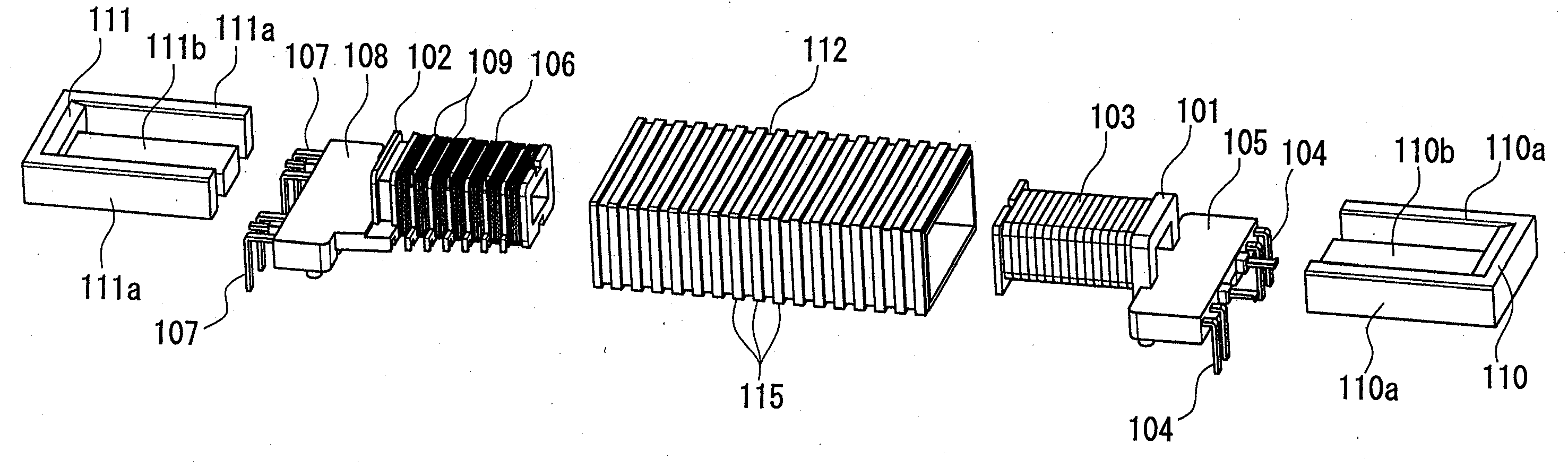
[0120]FIGS. 11 to 17 show a third embodiment in which an isolation transformer according to the present invention is used as an inverter transformer for causing a cold-cathode tube that forms a backlight for an LCD to emit light. In the isolation transformer, a bobbin is divided into a first bobbin 101 and a second bobbin 102.

[0121]The first bobbin 101 includes a winding portion which is made of an electrically insulating synthetic resin and shaped into a rectangular tube and around the outer circumference of which a primary coil 103 is wound and a terminal placement portion 105 having a substantially rectangular plate-like shape which is disposed at one end of the winding portion in the axial direction and which is studded with terminals 104 to which to an end of the primary coil 103 is connected, the winding portion and the terminal placement portion 105 integrally molded, as shown in FIGS. 11, 12, and 17. The terminal placement portion 105 is formed in such a way that a surface t...


PUM

PropertyMeasurementUnit
voltageaaaaaaaaaa
thicknessaaaaaaaaaa
magneticaaaaaaaaaa

Abstract

The present invention provides a transformer including a first bobbin (1) around which a primary coil (3) is wound, a second bobbin (2) which is disposed adjacent to the first bobbin (1) and around which a secondary coil (9) is wound, a core disposed across the first and second bobbins and forming a closed magnetic path. The core is divided into a first core (17) positioned on the side where the first bobbin is present and a second core (18) positioned on the side where the second bobbin is present, and an insulating member (14) is interposed in a magnetically coupled portion between the first core (17) and the second core (18), the insulating member (14) including outer circumference sheaths (16a) and (16b) that cover at least one of the first and second cores and a barrier (15) interposed between the opposing surfaces of the first and second cores.

Description

TECHNICAL FIELD[0001]The present invention relates to a high-voltage transformer that requires high insulating performance between the primary and secondary sides.BACKGROUND ART[0002]In general, safety standards require a variety of transformers to employ a structure in which a predetermined insulation distance (creepage distance) is ensured between a primary coil and a secondary coil.[0003]On the other hand, an inverter transformer that causes a cold-cathode tube incorporated as a light source in a liquid crystal display to discharge and emit light boosts the voltage inputted to a primary coil to a high voltage ranging from 1000 to 2000 V in a secondary coil and outputs the high voltage to the cold-cathode tube.[0004]An inverter transformer is therefore required to ensure insulation between the primary and secondary coils by providing a longer insulation distance therebetween than that provided in a typical low-voltage transformer. In a high-voltage isolation transformer in which a...

Claims


Application Information

Patent Timeline
Patent Type & Authority Applications(United States)
IPC IPC(8): H01F17/06
CPCH01F27/326H01F27/266
Inventor AKIYAMA, HIDEYUKIHIROHASHI, TOHRUHIRONAKA, KIYOSHI
Owner NJ COMPONENTS CO LTD
Why Eureka
Try Eureka