Wireless Physiology Monitor

a monitor and physiology technology, applied in the field of physiology measurement techniques and biotelemetry, can solve the problems of ct scanners suffering from numerous disadvantages, ekg does not produce an image of the heart itself, and is not a direct measurement of the motion,

Active Publication Date: 2010-09-30
MATHAI TOM +1
View PDF16 Cites 164 Cited by
  • Summary
  • Abstract
  • Description
  • Claims
  • Application Information

AI Technical Summary

Benefits of technology

[0009]The present invention overcomes these and other deficiencies of the prior art by providing a Doppler based physiological monitoring technique that implements modulated radio signals, such as IEEE 802.11(x) modulated signals, as a diagnostic signal. The differences between the source diagnostic and the return signal (i.e., the modified signal after undergoing modification as it passes through the patient) are then analyzed to monitor essential and typical life processes, activities, and functions such as, but not limited to measuring heart rate and detecting heart defects, and respiratory rate. For example, using Doppler Effect principles, heart rate and motion can be measured from the differences in frequency, phase, and / or wavelength between the source signal and the modified signal reflected back from the heart moving within the patient.

Problems solved by technology

The electrodes must be physically connected to the patient being monitored, which can be bothersome to the patient, for the duration of the EKG test.
In addition, an EKG does not produce an image of the heart itself and is not a direct measurement of the motion of the heart.
Yet, CT scanners suffer from numerous disadvantages.
They are expensive, bulky and immobile, require patients to remain generally immobile for extended periods of time during the scanning, and expose patients to potentially harmful x-rays.
As with CT scanners, MRI scanners are expensive, very large and immobile, and require patients to remain relatively immobile during the procedure.
Furthermore, MRI scanners cannot be used by some people with metal implants.

Method used


Image

  • Wireless Physiology Monitor
  • Wireless Physiology Monitor
  • Wireless Physiology Monitor

Examples


Embodiment Construction

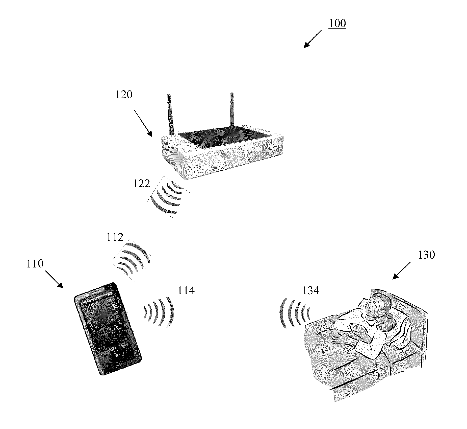
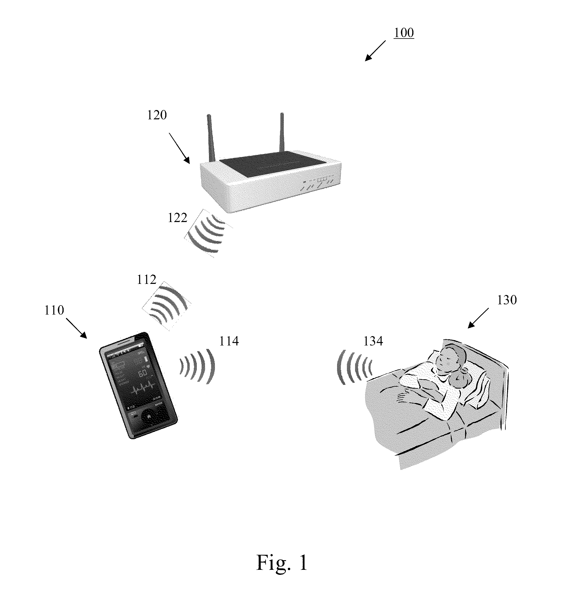
[0037]Further features and advantages of the invention, as well as the structure and operation of various embodiments of the invention, are described in detail below with reference to the accompanying FIGS. 1-21, wherein like reference numerals refer to like elements. Although the embodiments of the invention are described in the context of a radio frequency (RF) modulated carrier, such as any one of the family of IEEE 802.11(x) protocols (more commonly referred to as WiFi), one of ordinary skill in the art readily appreciates that any type of modulated communication signal can be implemented for the investigation of physiological functions within a patient. For example, the inventive concepts described herein may be implemented using any modulated or wireless communications protocol such as, but not limited to Bluetooth, WiMax (Worldwide Interoperability for Microwave Access), CDMA (Code Division Multiple Access), GSM (Global System for Mobile Communication), and 3GPP LTE (Long Ter...


PUM


Abstract

The present invention provides a new non-invasive technique for organ, e.g., heart and lung, monitoring. In at least one embodiment of the invention, a subject is radiated with a non-harmful and relatively low power electromagnetic source diagnostic signal normally associated with a communications protocol such as, but not limited to a version of the IEEE 802.11(x) family of protocols in the 2.4, 3.6, or 5 GHz spectrum bands. After passing through the patient, a return signal is acquired from the patient and compared to the original source signal. The differences between the source and modified signals are then analyzed to monitor the heart, e.g., measure heart rate and detect defects within the heart, and the lung. For example, using Doppler Effect principles, heart rate and motion can be measured from the differences in frequency, phase, and/or wavelength between the source signal and the modified signal reflected back from the heart moving within the patient.

Description

CROSS-REFERENCE TO RELATED APPLICATIONS[0001]The present application claims priority under 35 U.S.C. §119(e) to U.S. Provisional Patent Application No. 61 / 155,510, entitled “WiFi OFDM Modulated Carrier for Heart and Lung Monitoring,” filed Feb. 25, 2009, and U.S. Provisional Patent Application No. 61 / 179,605, entitled “Fall Detection and Heart / Lung Monitoring,” filed May 19, 2009, the disclosures of which are incorporated by reference herein in their entirety.BACKGROUND OF THE INVENTION[0002]1. Field of Invention[0003]The present invention relates to physiological measurement techniques and biotelemetry (i.e., medical telemetry), and more particularly to a system, device, and method for heart and lung monitoring using a modulated radio frequency (RF) carrier, such as an IEEE 802.11(x) (“WiFi”) orthogonal frequency-division multiplexing (OFDM) signal, as a diagnostic signal.[0004]2. Description of Related Art[0005]Several technologies have been developed to help doctors and medical p...

Claims


Application Information

Patent Timeline
Patent Type & Authority Applications(United States)
IPC IPC(8): G08B23/00G16H40/67
CPCA61B5/024A61B5/05G01S13/56A61B5/7207G01S7/003A61B5/113A61B5/0507A61B5/725A61B5/7278A61B5/002A61B5/0022A61B5/02028A61B5/0205A61B5/02405A61B5/0816G16H40/67
Inventor SINGH, RABINDRARENUKANAND, GUBBI UMESHMARGON, KENNETHRAHMAN, MD MIJANUR
Owner MATHAI TOM
Why Eureka
Try Eureka