

Instrument for use with fluid
- Summary
- Abstract
- Description
- Claims
- Application Information
AI Technical Summary
Benefits of technology
Problems solved by technology
Method used
Image

Examples
Embodiment Construction
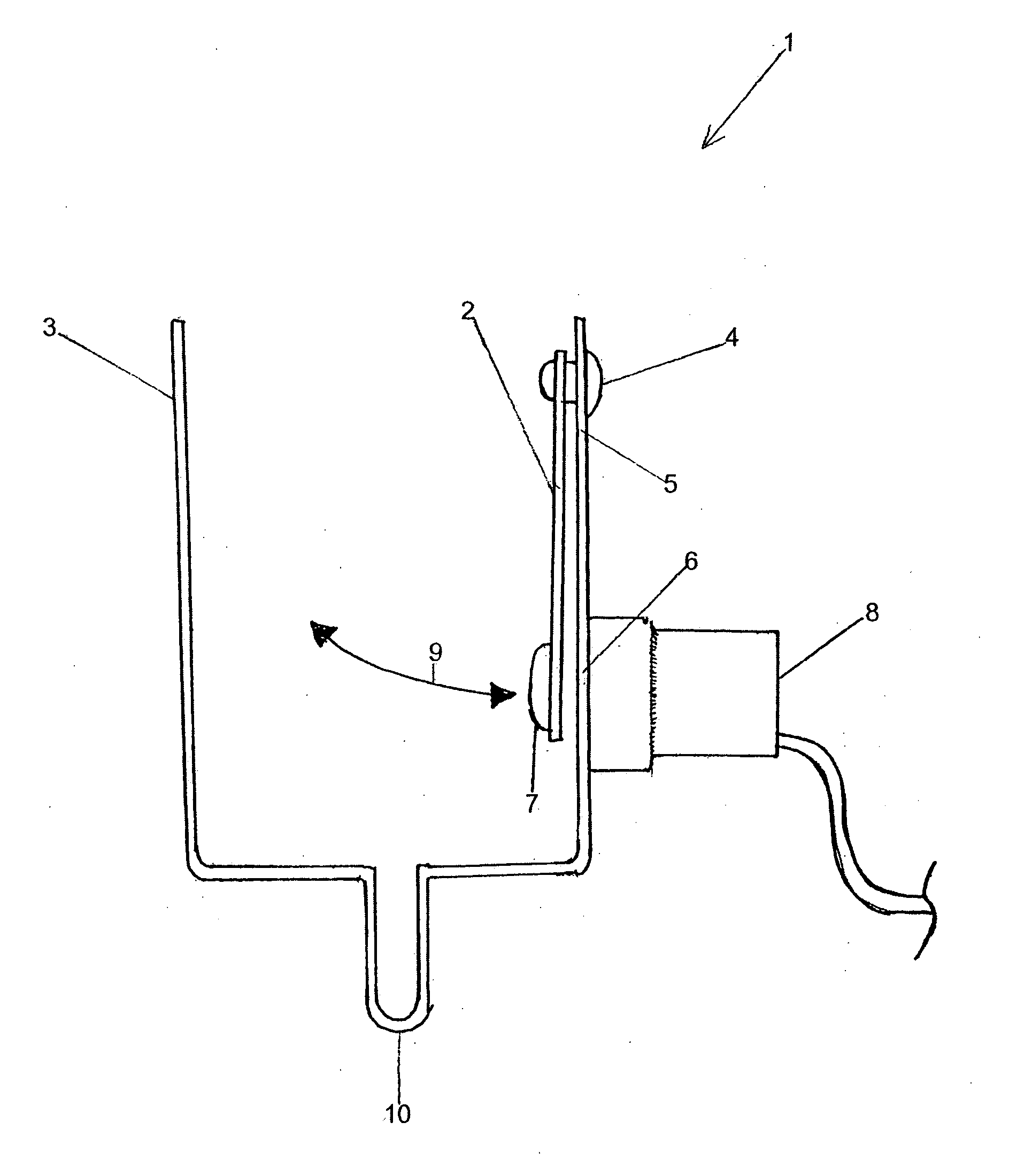
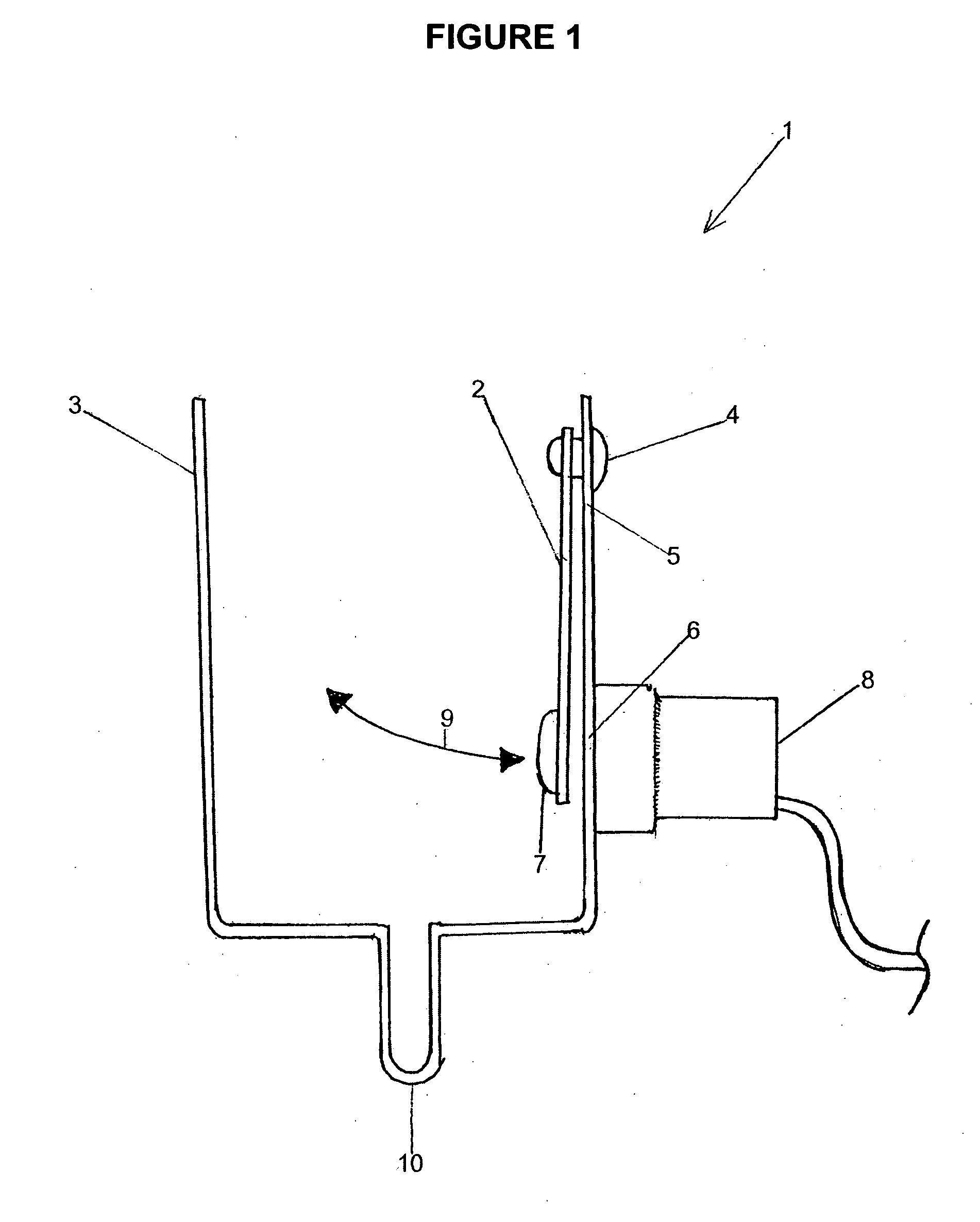
[0122]FIG. 1 illustrates the present invention (indicated generally by arrow 1), which includes the strap (2) mounted to the interior of a sample cell (3) via a fastener (4).
[0123]A spacer (5) ensures that the body of the strap (2) is kept from making contact with the side wall of the container (6). This spacer (5) also acts as a fulcrum for the motion of the strap (2).
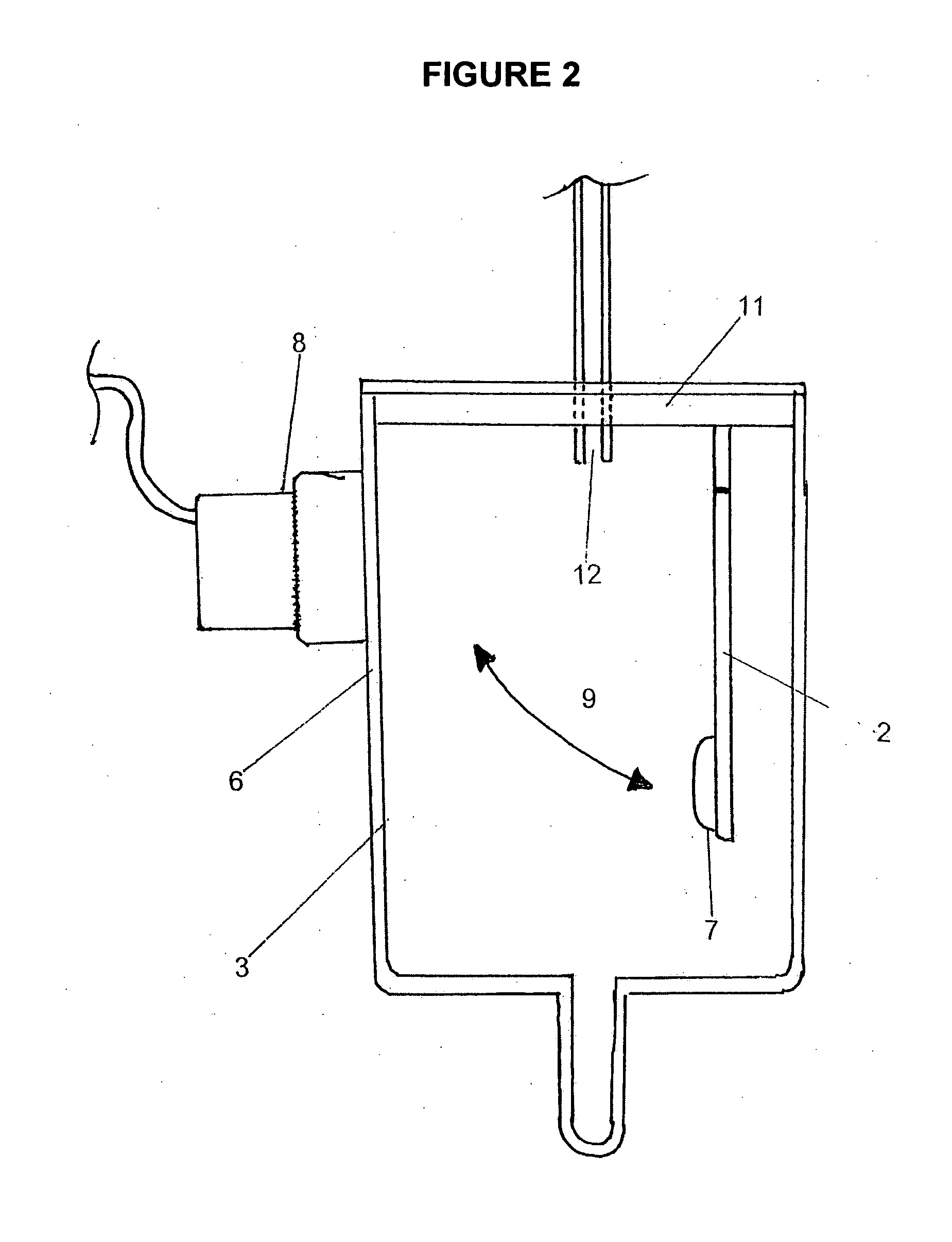
[0124]At the tip of the strap (2) there is provided a magnet (7). On the exterior side of the cell (3) closest to the magnet (7) is an electromagnetic coil (8). The face (not shown) of the electromagnetic coil (8) is secured to the side wall of the cell (6) by adhesive.
[0125]In use, the electromagnetic coil generates a magnetic field, causing the strap to move in the path of travel indicated by arrow 9, as it is repelled by the electromagnetic coil (8). It should be appreciated that this path of travel does not inhibit the inlet / outlet (10) of the cell, permitting passage of additional fluids if required.
[0126]Another...
PUM
| Property | Measurement | Unit |
|---|---|---|
| Weight | aaaaa | aaaaa |
| Time | aaaaa | aaaaa |
| Magnetism | aaaaa | aaaaa |
Abstract
Description
Claims
Application Information