Biasing circuit for a microelectromechanical acoustic transducer and related biasing method

a biasing circuit and microelectromechanical technology, applied in the direction of amplifiers, instruments, electric variable regulation, etc., can solve the problems of long start-up time, reduced signal-to-noise ratio, and easy shortening of the settling time of such a configuration,

Active Publication Date: 2010-09-30
STMICROELECTRONICS SRL
View PDF6 Cites 75 Cited by
  • Summary
  • Abstract
  • Description
  • Claims
  • Application Information

AI Technical Summary

Problems solved by technology

This circuit arrangement is, however, considerably limited by the reduced signal-to-noise ratio since, during normal operation, both a possible “ripple” at the output of the charge-pump stage 8 and the noise generated by the same charge pump add, without any attenuation, to the electrical signal generated by the MEMS microphone 1 as a function of the detected acoustic signal.
The main problem of such a circuit architecture is represented by the long start-up time of the biasing circuit in general and of the low-pass filter 12 in particular, principally due to the presence of the pair of diodes connected in anti-parallel configuration and to the high resistance provided thereby.
The settling time of such a configuration can easily last mi

Method used


Image

  • Biasing circuit for a microelectromechanical acoustic transducer and related biasing method
  • Biasing circuit for a microelectromechanical acoustic transducer and related biasing method
  • Biasing circuit for a microelectromechanical acoustic transducer and related biasing method

Examples


Embodiment Construction

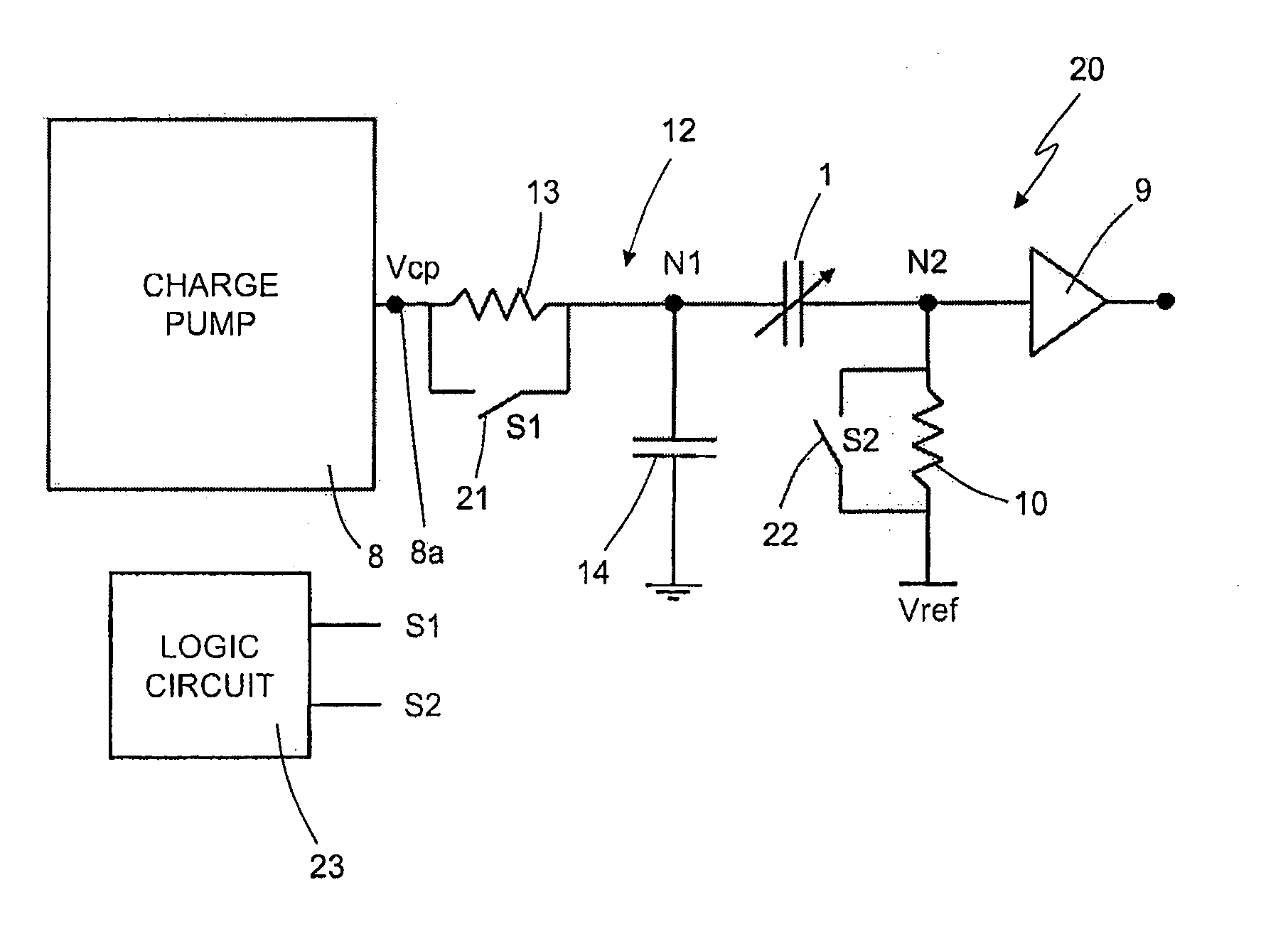
[0034]As will be clarified hereinafter, one aspect of the present disclosure envisages introduction, for the biasing circuit of an acoustic transducer, in particular a MEMS microphone of a capacitive type, of an operating state during a start-up step (occurring upon turning-on or return from a power-down condition), in which one or both of the terminals of the MEMS microphone are brought directly to desired biasing voltages so as to enable a rapid settling of the voltages of the same terminals (and an initialization of a filtering stage coupled to the acoustic transducer). At the end of the start-up step (which can consequently be much faster than in traditional solutions), one or both of the terminals of the MEMS microphone are connected to a high impedance, whether it is associated to a filter resistor or to the input of a corresponding reading amplifier stage.

[0035]In particular, as illustrated in FIG. 7 (where elements that are similar to others already described are designated ...


PUM


Abstract

A biasing circuit for an acoustic transducer is provided with: a voltage-booster stage, which supplies, on a biasing terminal, a boosted voltage for biasing a first terminal of the acoustic transducer; and filtering elements, set between the biasing terminal and the acoustic transducer, for filtering disturbances on the boosted voltage. The biasing circuit is further provided with switches, which can be actuated so as to connect the first terminal to the biasing terminal of the voltage-booster stage, directly during a start-up step of the biasing circuit, and through the filtering elements at the end of the start-up step.

Description

BACKGROUND[0001]1. Technical Field[0002]The present disclosure relates to a biasing circuit for an acoustic transducer, in particular a capacitive microphone of a MEMS (Microelectro-Mechanical System) type, to which the ensuing treatment will make explicit reference, without this implying any loss of generality. The present disclosure further relates to a method for biasing the acoustic transducer.[0003]2. Description of the Related Art[0004]As is known, an acoustic transducer of a capacitive type, for example a MEMS microphone, generally comprises a mobile electrode, in the form of a diaphragm or membrane, set facing a fixed electrode, so as to provide the plates of a variable-capacitance sensing capacitor. The mobile electrode is generally anchored, by means of a perimetral portion thereof, to a substrate, whilst a central portion thereof is free to move or bend in response to the pressure exerted by incident sound waves. The mobile electrode and the fixed electrode form a capacit...

Claims


Application Information

Patent Timeline
IPC IPC(8): H03F99/00H02B1/00
CPCG05F1/467H02M3/07
Inventor DAVID, FILIPPOGASPARINI, ALESSANDRO
Owner STMICROELECTRONICS SRL
Why Eureka
Try Eureka