Intentionally mistuned integrally bladed rotor

a rotor and integral technology, applied in the direction of propellers, propulsive elements, water-acting propulsive elements, etc., can solve the problems of increasing the flutter susceptibility between the blades and the solution is not fully satisfactory from an aerodynamic perspectiv

Active Publication Date: 2010-09-30
PRATT & WHITNEY CANADA CORP
View PDF17 Cites 52 Cited by
  • Summary
  • Abstract
  • Description
  • Claims
  • Application Information

AI Technical Summary

Benefits of technology

[0007]In a third aspect, there is provided a method of reducing vibration in an gas turbine engine integrally bladed rotor (IBR) having a circumferential row of blades extending integrally from a hub, the circumferential row of blades comprising an even number of blades; the method comprising varying the natural frequency of the blades around the hub in an alternate pattern by providing first and second distinct airfoil profiles around the hub, the first and second profiles having similar suction side, leading edge and trailing edge profiles but a different pressure side profile.

Problems solved by technology

However, it has been found that the uniformity between the blades increases flutter susceptibility.
However, this solution is not fully satisfactory from an aerodynamic and a manufacturing point of view.

Method used


Image

  • Intentionally mistuned integrally bladed rotor
  • Intentionally mistuned integrally bladed rotor
  • Intentionally mistuned integrally bladed rotor

Examples


Embodiment Construction

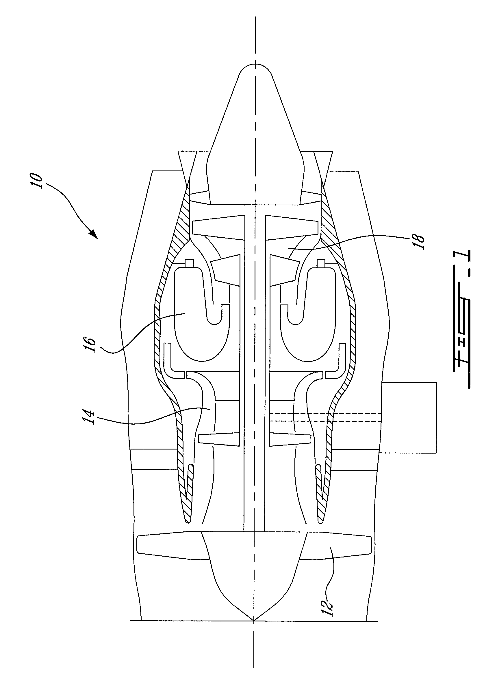
[0012]FIG. 1 illustrates a turbofan gas turbine engine 10 of a type preferably provided for use in subsonic flight, generally comprising in serial flow communication a fan 12 through which ambient air is propelled, a multistage compressor 14 for pressurizing the air, a combustor 16 in which the compressed air is mixed with fuel and ignited for generating an annular stream of hot combustion gases, and a turbine section 18 for extracting energy from the combustion gases.

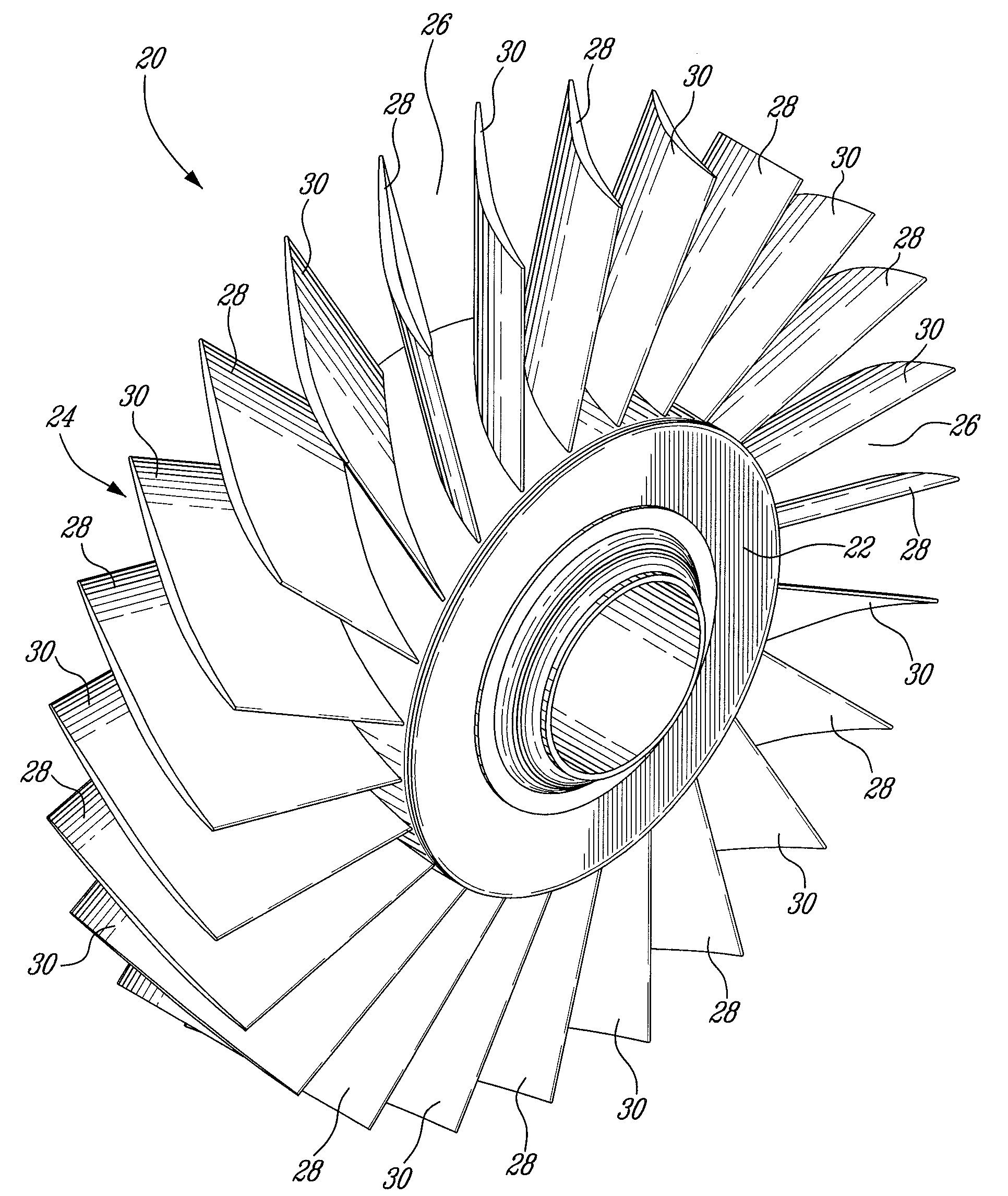
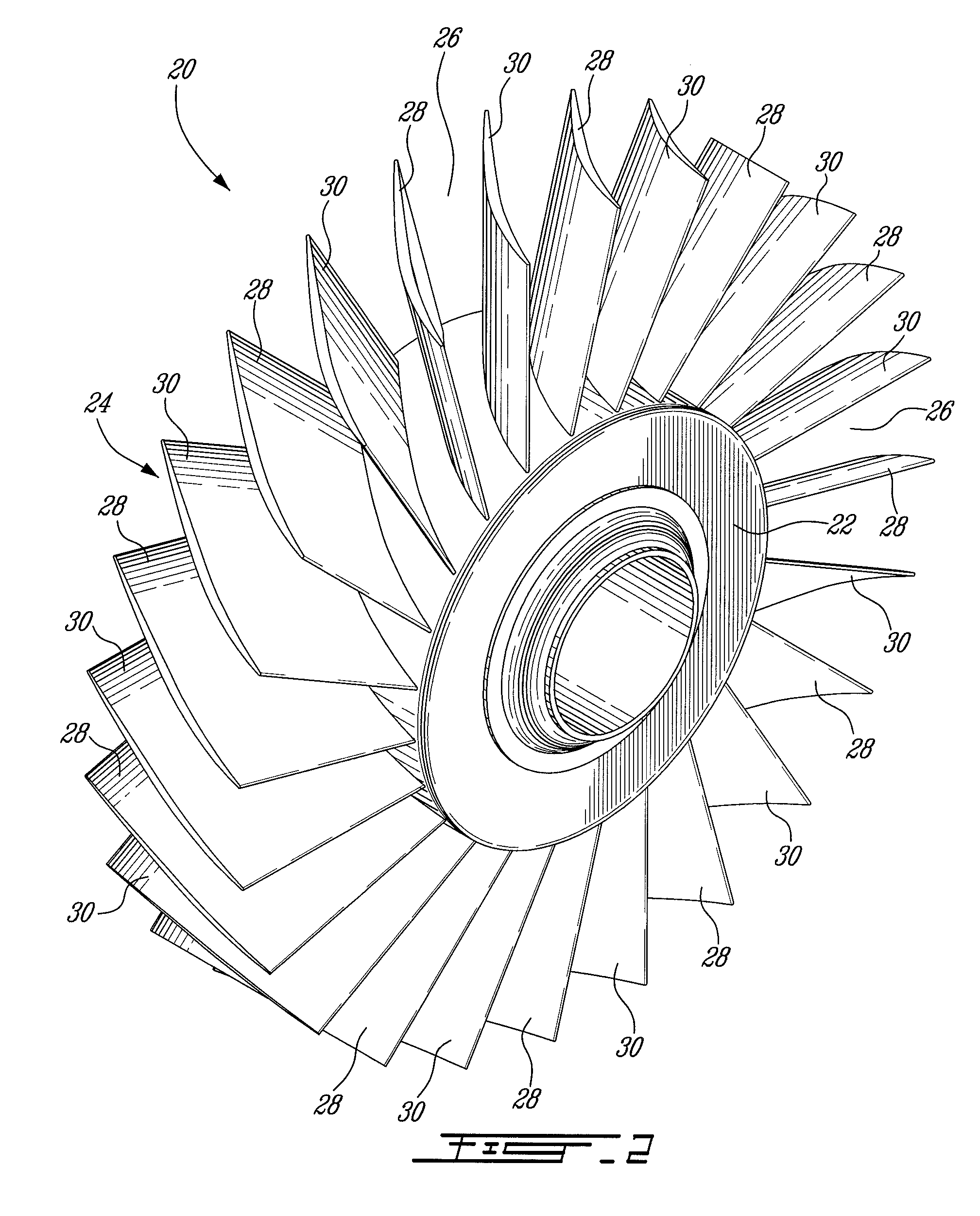
[0013]FIG. 2 illustrates an integrally bladed rotor (IBR) 20 that could be used in the fan or compressor section of the engine 10 shown in FIG. 1. The IBR 20 has a hub 22 and a circumferential row of blades 24 extending integrally from the hub 22, the adjacent blades defining interblade passages 26 for the working fluid. The hub 22 and the blade row 24 can be flank milled or point milled from a same block of material.

[0014]The blade row 24 has an even number of blades and is composed of two groups of blades 28 and 30 w...


PUM


Abstract

A frequency mistuned integrally bladed rotor (IBR) for a gas turbine engine comprises a hub and a circumferential row of blades of varying frequency projecting integrally from the hub. Each blade in the row alternate with another blade having a different pressure surface definition but similar suction surface, leading edge and trailing edge definitions.

Description

TECHNICAL FIELD[0001]The application relates generally to gas turbine engines and, more particularly, to a frequency mistuned integrally bladed rotor (IBR).BACKGROUND OF THE ART[0002]Integrally bladed rotors (IBR), also known as blisks, comprises a circumferential row of blades integrally formed in the periphery of a hub. The blades in the row are typically machined such as to have the same airfoil shape. However, it has been found that the uniformity between the blades increases flutter susceptibility. Flutter may occur when two or more adjacent blades in a blade row vibrate at a frequency close to their natural vibration frequency and the vibration motion between the adjacent blades is substantially in phase.[0003]One solution proposed in the past to avoid flutter instability is to mistune the IBR by cropping the leading edge tip of some of the blades around the hub. However, this solution is not fully satisfactory from an aerodynamic and a manufacturing point of view.[0004]Accord...

Claims


Application Information

Patent Timeline
Patent Type & Authority Applications(United States)
IPC IPC(8): F01D25/04F01D5/14
CPCF01D5/10F01D5/16Y10S416/50F05D2260/96F05D2260/961
Inventor KELLY, FRANKHEIKURINEN, KARIFAZARI, EDWARDWU, YUHUA
Owner PRATT & WHITNEY CANADA CORP
Why Eureka
Try Eureka