Surgical navigation system with wireless magnetoresistance tracking sensors

a technology of wireless magnetoresistance tracking and surgical navigation system, applied in the field of surgical navigation system, can solve the problems of optical sensors not being optical navigation system is less accurate and unreliable when considering, optical sensors cannot be located inside the body,

Inactive Publication Date: 2010-09-30
GENERAL ELECTRIC CO
View PDF36 Cites 132 Cited by
  • Summary
  • Abstract
  • Description
  • Claims
  • Application Information

AI Technical Summary

Problems solved by technology

This limitation prevents optical sensors from being located inside the body.
Even though the tip position of a rigid instrument or other medical device having these sensors attached thereto may be extrapolated, an optical navigation system is therefore, less accurate and unreliable when considering the opportunities for errors inherent in these systems.
Optical sensors may be wireless, but they cannot be made small enough to be located at the tip of an instrument or medical device to be inserted into a patient's body in a minimally invasive manner.
Optical tracking sensors may not be used because they require unrestricted line-of-site pathway between the optical target and the image receptor.
While coil based EM sensors have been successfully implemented, they suffer from poor signal-to-noise ratio (SNR) as the transmitter coil frequency is reduced and / or the receiver coil volume is reduced.
Reducing the SNR translates into a reduced effective tracking range (distance from transmitter to receiver) of the EM sensors that may result in a clinically meaningful position error.
Another problem typically associated with coil based EM sensors is that they are susceptible to magnetic field distortions that arise from eddy currents in nearby conducting objects.
Therefore, unpredictable disturbances resulting from metallic objects in the magnetic field reduce the accuracy or may even render the tracking technique useless.
Selecting a magnetic field frequency as low as the application allows reduces problems resulting from eddy currents, however it also reduces the sensitivity of coil based EM sensors since these are based on induction.
Other problems associated with coil based EM sensors is that they are difficult and expensive to manufacture and are also inherently sensitive to parasitic inductance and capacitance from the cables, connectors and electronics because the sensor signal is proportionally smaller while the parasitic signal remains the same.
Therefore, it is impossible to distinguish between the actual sign and parasitic signal when using a phase-sensitive measurement.
While some of the parasitic contributions may be partially nulled out using more expensive components and manufacturing processes, the remaining parasitic inductance and capacitance result in a reduced range.
While these sensors are compact and relatively inexpensive, they are highly prone to drift and have a small dynamic range.
However these sensors are expensive, bulky and have a relatively small dynamic range.
They are also expensive with significant operating costs since they require cryogens or a high-power closed-cycle cooling system.

Method used


Image

  • Surgical navigation system with wireless magnetoresistance tracking sensors
  • Surgical navigation system with wireless magnetoresistance tracking sensors
  • Surgical navigation system with wireless magnetoresistance tracking sensors

Examples


Embodiment Construction

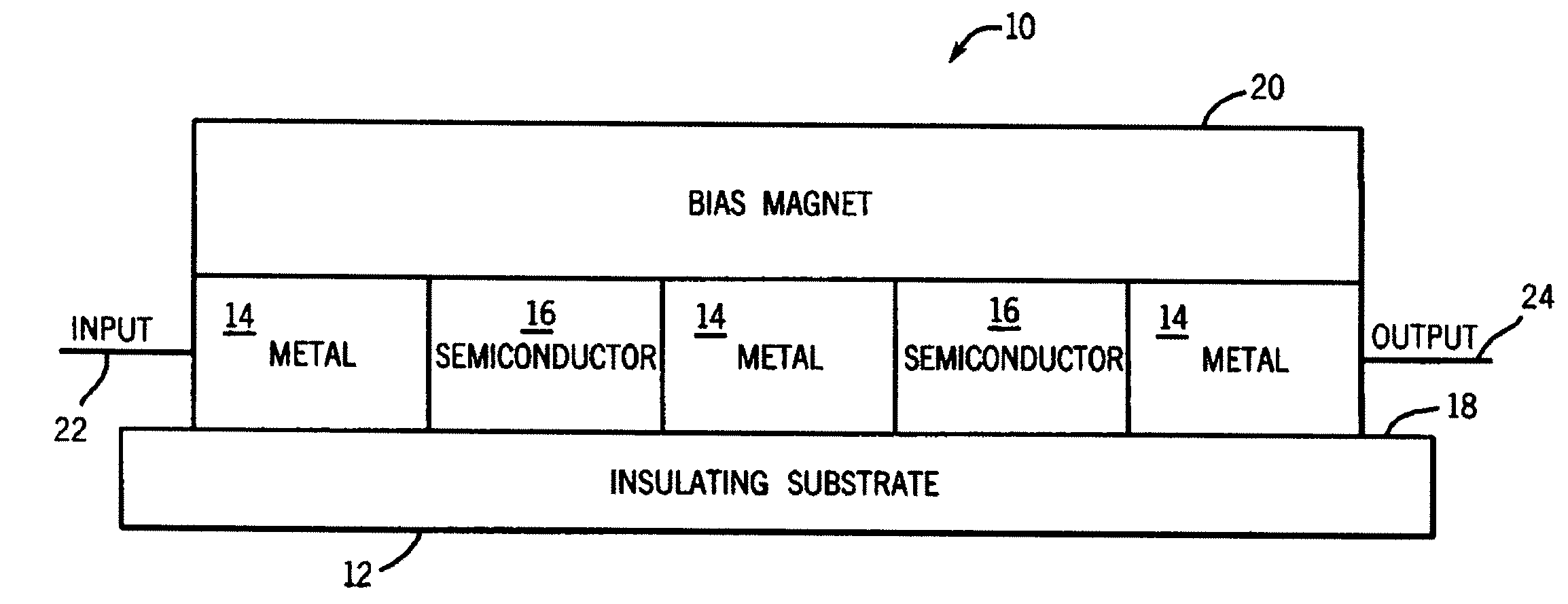
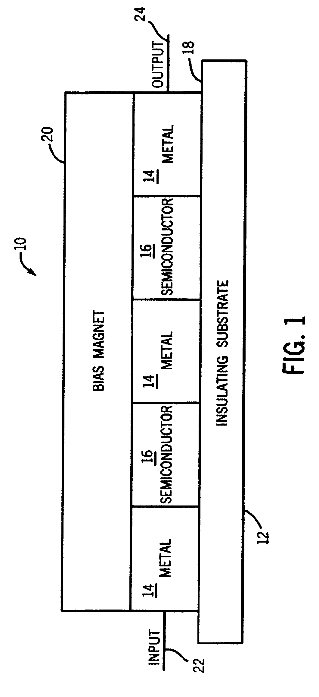
[0021]Referring now to the drawings, FIG. 1 illustrates an enlarged side view of an exemplary embodiment of a magnetoresistance sensor 10. A magnetoresistance device is a device that provides a change in electrical resistance of a conductor or semiconductor when a magnetic field is applied. The device's resistance depends upon the magnetic field applied. As shown in FIG. 1, the a magnetoresistance sensor 10 comprises an insulating substrate 12, an alternating pattern of a metal material 14 and a semiconductor material 16 deposited on a surface 18 of the insulating substrate, and a bias magnet material 20 deposited over the alternating pattern of metal material 14 and semiconductor material 16. The alternating pattern of metal material 14 and semiconductor material 16 creates a composite structure with alternating bands of metal material 14 and semiconductor material 16. At least one input connection contact 22 is coupled to the metal material 14 and at least one output connection co...


PUM


Abstract

A surgical navigation system having one or more wireless magnetoresistance sensors, where the sensors have the noise and dynamic range appropriate for position and orientation tracking. The surgical navigation system comprising at least one wireless magnetoresistance reference sensor rigidly attached to at least one anatomical reference of a patient, at least one wireless magnetoresistance sensor attached to at least one device, and at least one processor for determining the position and orientation of the at least one device.

Description

BACKGROUND OF THE INVENTION[0001]This disclosure relates generally to surgical navigation systems for use in minimally invasive surgeries, and more particularly to a surgical navigation system utilizing wireless magnetoresistance tracking sensors.[0002]Surgical navigation systems track the precise position and orientation of surgical instruments, implants or other medical devices in relation to multidimensional images of a patient's anatomy. Additionally, surgical navigation systems use visualization tools to provide the surgeon with co-registered views of these surgical instruments, implants or other medical devices with the patient's anatomy.[0003]The multidimensional images may be generated either prior to or during the surgical procedure. For example, any suitable medical imaging technique, such as X-ray, computed tomography (CT), magnetic resonance (MR), positron emission tomography (PET), ultrasound, or any other suitable imaging technique, as well as any combinations thereof ...

Claims


Application Information

Patent Timeline
Patent Type & Authority Applications(United States)
IPC IPC(8): A61B5/05
CPCA61B5/061A61B5/065A61B2019/5272A61B19/5244A61B2019/5251A61B5/073A61B34/20A61B2034/2051A61B2034/2072
Inventor JENSEN, VERNON THOMASHUBER, WILLIAM HULLINGER
Owner GENERAL ELECTRIC CO
Why Eureka
Try Eureka