Vehicular steering control apparatus and method

a control apparatus and steering control technology, applied in the direction of motor control for motor oscillation damping, non-deflectable wheel steering, underwater vessels, etc., can solve the problems of inability to meet the requirement, the carrier frequency cannot be appropriately set in accordance with the traveling state of the vehicle, etc., to reduce the switching loss of the inverter, reduce the noise of the inverter, and reduce the effect of the switching loss

Inactive Publication Date: 2010-09-30
HITACHI AUTOMOTIVE SYST LTD
View PDF9 Cites 34 Cited by
  • Summary
  • Abstract
  • Description
  • Claims
  • Application Information

AI Technical Summary

Benefits of technology

[0007]It is, therefore, an object of the present invention to provide vehicular steering control apparatus and method which are capable of reducing the switching loss of the inverter when a high output of the electric motor generating the steering force is required.
[0008]According to one aspect of the present invention, there is provided a vehicular steering control apparatus, comprising: a steering mechanism configured to steer steerable wheels of a vehicle according to a steering force; an electric motor configured to be drivingly controlled to provide the steering force for the steering mechanism; a steering quantity calculation section configured to calculate a manipulated variable of the electric motor; a PWM control section configured to generate a PWM control signal to drive the electric motor on a basis of the manipulated variable of the electric motor; an inverter configured to supply an electric power to the electric motor according to switching operations thereof based on the PWM control signal; and a carrier frequency control section configured to control a carrier frequency of the PWM control signal, wherein the carrier frequency control section is configured to set the carrier frequency to at least two predetermined set frequencies in accordance with at least one of a driving state of the electric motor and a traveling state of the vehicle, one of the predetermined set frequencies being set to reduce noises in the inverter and the other of the predetermined set frequencies being set to reduce a switching loss in the inverter.
[0009]According to another aspect of the present invention, there is provided a vehicular steering control method comprising: providing a steering mechanism configured to steer steerable wheels of a vehicle according to a steering force; providing an electric motor configured to be drivingly controlled to provide the steering force for the steering mechanism; calculating a manipulated variable of the electric motor; generating a PWM control signal to drive the electric motor on a basis of the manipulated variable of the electric motor; providing an inverter for supplying an electric power to the electric motor according to switching operations thereof based on the PWM control signal; and controlling a carrier frequency of the PWM control signal,wherein, during the control of the carrier frequency, the carrier frequency is set to at least two predetermined set frequencies in accordance with at least one of a driving state of the electric motor and a traveling state of the vehicle, one of the predetermined set frequencies being set to reduce noises in the inverter and the other of the predetermined set frequencies being set to reduce a switching loss in the inverter.

Problems solved by technology

Hence, if this technique were merely applied to a steering control apparatus, the carrier frequency could not appropriately be set in accordance with a traveling state of the vehicle.
In such a case of an avoidance traveling of a collision of an object or of a low-speed traveling where a high output is required for the electric motor which generates a steering force, there is a possibility that this requirement cannot be satisfied due to the switching loss in the inverter.

Method used


Image

  • Vehicular steering control apparatus and method
  • Vehicular steering control apparatus and method
  • Vehicular steering control apparatus and method

Examples


first embodiment

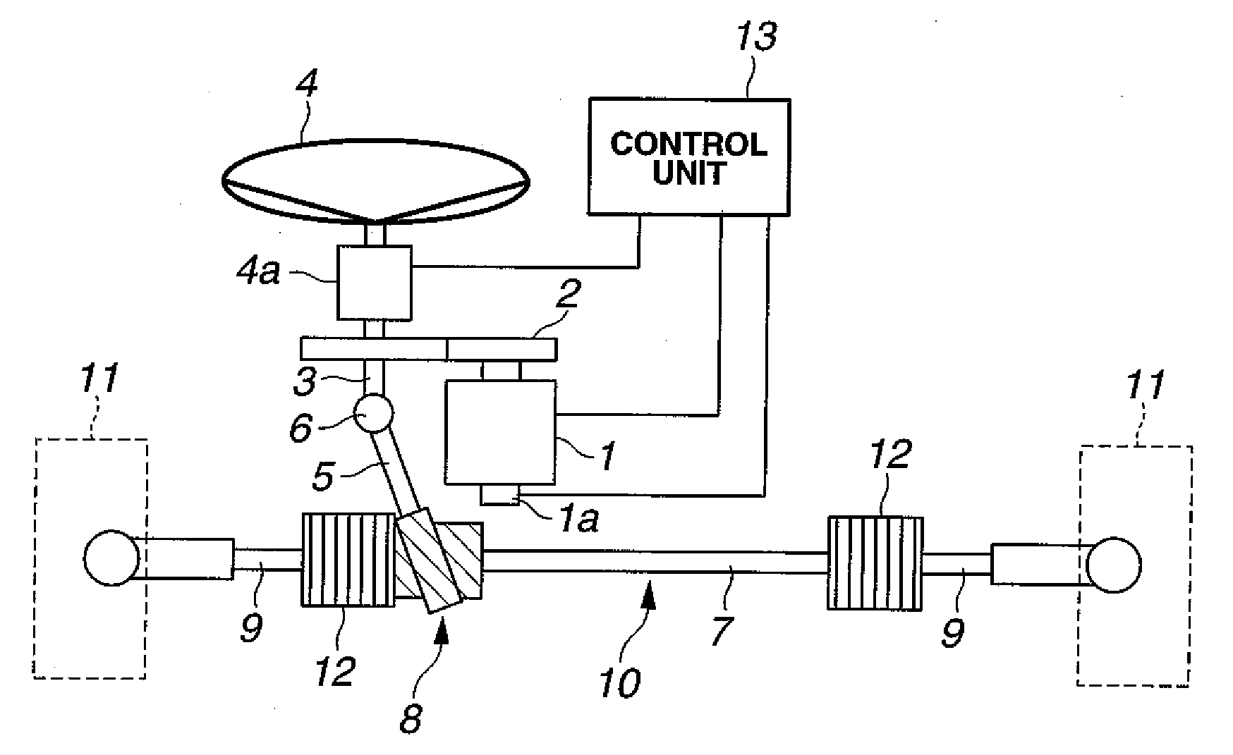
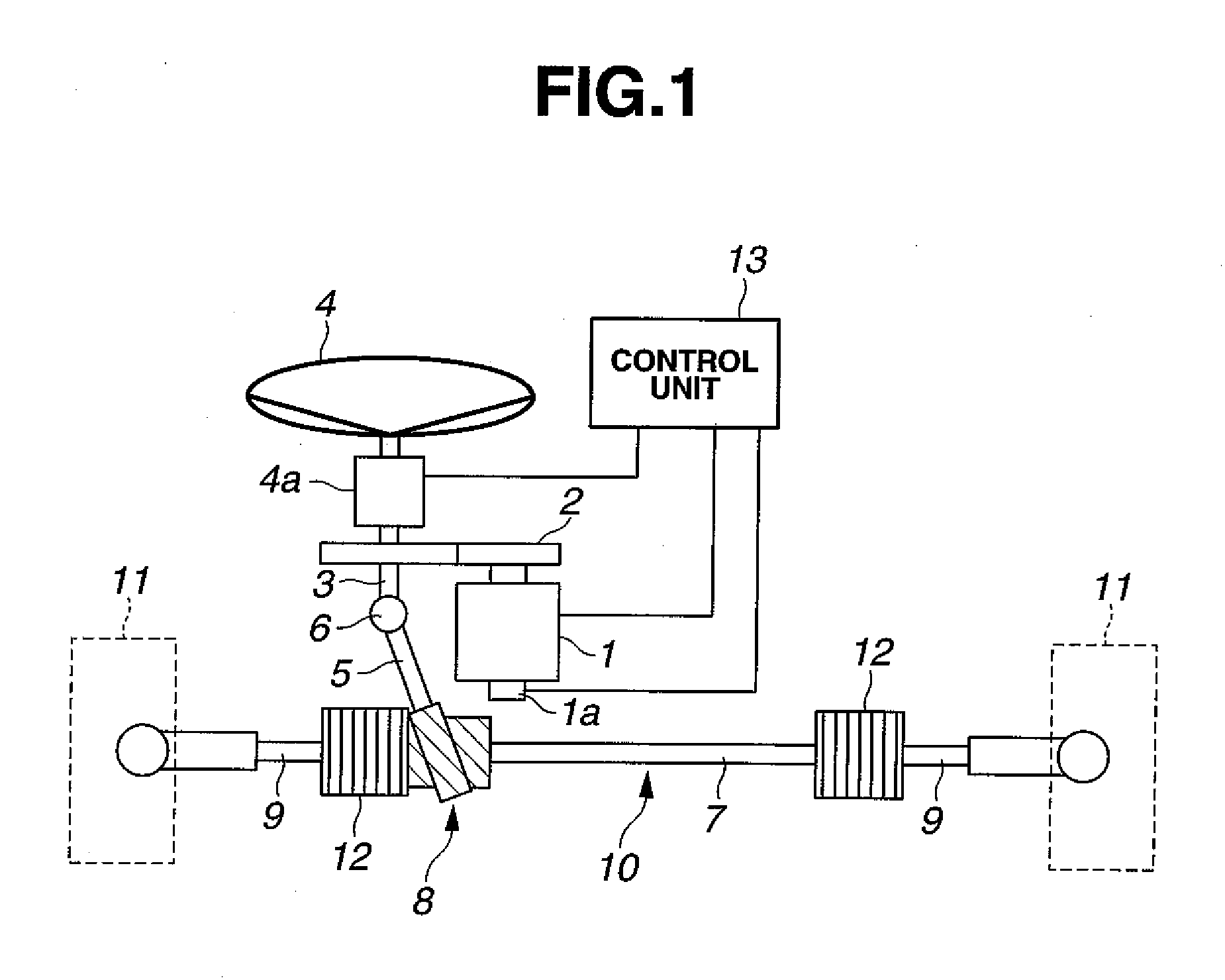
[0040]FIG. 1 shows a configuration view of an electric power steering apparatus to which a vehicular steering control apparatus according to the present invention is applicable, as a first preferred embodiment according to the present invention.

[0041]The electric power steering apparatus shown in FIG. 1 is, so-called, of an assistance torque type in which an assistance torque generated by an electric motor 1 driven by an electric power of a three-phase alternating current transmitted to a steering shaft 3 via a speed reducer 2. A steering wheel 4 which is rotated as a unit with steering shaft 3 is provided on one end of steering shaft 3. On the other hand, a pinion shaft 5 is linked with the other end of steering shaft 3 via a universal joint 6.

[0042]Pinion shaft 5 constitutes a steering gear 8 of, so-called, rack-and-pinion type together with a rack bar 7. In other words, when steering wheel 4 is rotated together with pinion shaft 5, a rotary motion of pinion shaft 5 is transformed...

second embodiment

[0062]FIG. 6 shows a detailed functional block diagram of control unit 13 representing a second preferred embodiment of the vehicular steering control apparatus according to the present invention. In the second embodiment shown in FIG. 6, current sensor 29 is installed to detect primary current Ib flowing through cable 14a and carrier generating section 30, which is the carrier frequency control section, sets the carrier frequency on a basis of primary current Ib received from current sensor 29. It should be noted that the other parts are the same as the first preferred embodiment described above.

[0063]FIG. 7 shows a graph representing a relationship between rotational speed ω and primary current Ib in a case where electric motor 1 is driven at the generable maximum torque together with an N (rotational speed)-T (torque) characteristic of electric motor 1. As shown in FIG. 7, primary current Ib is increased together with the increase in rotational speed ω of electric motor 1 or the ...

third embodiment

[0069]FIG. 9 shows a functional block diagram of control unit 13 representing a third preferred embodiment according to the present invention. A voltage sensor 31 to detect an input voltage Vi to be supplied to inverter 13b is installed in the third embodiment, as shown in FIG. 9. The carrier frequency is set by carrier generating section 32, which is the carrier frequency control section, in accordance with an output of voltage sensor 31. The other parts are approximately the same as those in the first embodiment.

[0070]FIG. 10 shows a graph representing a relationship between rotational speed ω and input voltage Vi in a case where electric motor 1 is driven at the maximum generable torque together with the N-T characteristic of electric motor 1. As shown in FIG. 10, if rotational speed ω of electric motor 1 or output thereof is increased, the current flowing through a harness 14a becomes large so that a voltage drop quantity in harness 14a is increased and, thus, input voltage Vi i...


PUM


Abstract

In vehicular steering control apparatus and method, a carrier frequency of a PWM control signal to drive an electric motor on a basis of the manipulated variable of the electric motor is controlled and the carrier frequency is set to at least two predetermined set frequencies in accordance with at least one of a driving state of the electric motor and a traveling state of the vehicle, one of the predetermined set frequencies being set to reduce noises in the inverter and the other of the predetermined set frequencies being set to reduce a switching loss in the inverter. For example, the carrier frequency is set to be lowered to the other of the predetermined set frequencies in a case where a rotational speed of the electric motor is driven in a rotational speed region (A2) higher than that in a constant torque region (A1).

Description

BACKGROUND OF THE INVENTION[0001](1) Field of the Invention[0002]The present invention relates to vehicular steering control apparatus and method which drivingly control an electric motor to provide a steering force for a steering mechanism which steers vehicular steerable wheels.[0003](2) Description of Related Art[0004]In a case where an electric motor is driven by means of a PWM (Pulse Width Modulation) control of an inverter, noises are generated due to switching operations of the inverter in accordance with a carrier frequency of a PWM control signal. In order to reduce the noises in the inverter, it is effective to set a carrier frequency at a non-audible frequency higher than an audible frequency. However, such a problem that, if the carrier frequency of the inverter is increased, a frequency of the switching operations in the inverter is increased and a switching loss is, thus, increased. As described hereinabove, since a trade-off relationship is established between a reduc...

Claims


Application Information

Patent Timeline
Patent Type & Authority Applications(United States)
IPC IPC(8): G06F19/00H02P6/10H02P21/14B62D6/00B62D5/00B62D5/04H02P6/06H02P6/08H02P6/17H02P6/28H02P21/00H02P21/05H02P21/18H02P21/22H02P21/24H02P23/04H02P25/03H02P27/08
CPCB62D5/046H02P21/145H02P6/10B62D5/0463H02P27/085H02P21/16
Inventor MATSUMURA, TATSUOSASAKI, MITSUOTAKAHASHI, TORU
Owner HITACHI AUTOMOTIVE SYST LTD
Why Eureka
Try Eureka