Fuel injection detecting device

a detection device and fuel injection technology, applied in the direction of electrical control, process and machine control, instruments, etc., can solve the problems of large pulsations of pressure waveform and differential value, disturbance of pressure waveform, and inability to accurately compute firr timing and firds timing

Active Publication Date: 2010-09-30
DENSO CORP
View PDF15 Cites 36 Cited by
  • Summary
  • Abstract
  • Description
  • Claims
  • Application Information

AI Technical Summary

Problems solved by technology

Thus, according to the above described computing method, the MFIRR timing and the FIRDS timing can not be accurately computed.
The pulsations of the pressure waveform and the differential value become large and an erroneous detection of the MFIRR timing and the FIRDS timing may b

Method used


Image

  • Fuel injection detecting device
  • Fuel injection detecting device
  • Fuel injection detecting device

Examples


first embodiment

[0047]First, it is described about an internal combustion engine to which a fuel injection detecting device is applied. The internal combustion engine is a multi-cylinder four stroke diesel engine which directly injects high pressure fuel (for example, light oil of 1000 atmospheres) to a combustion chamber.

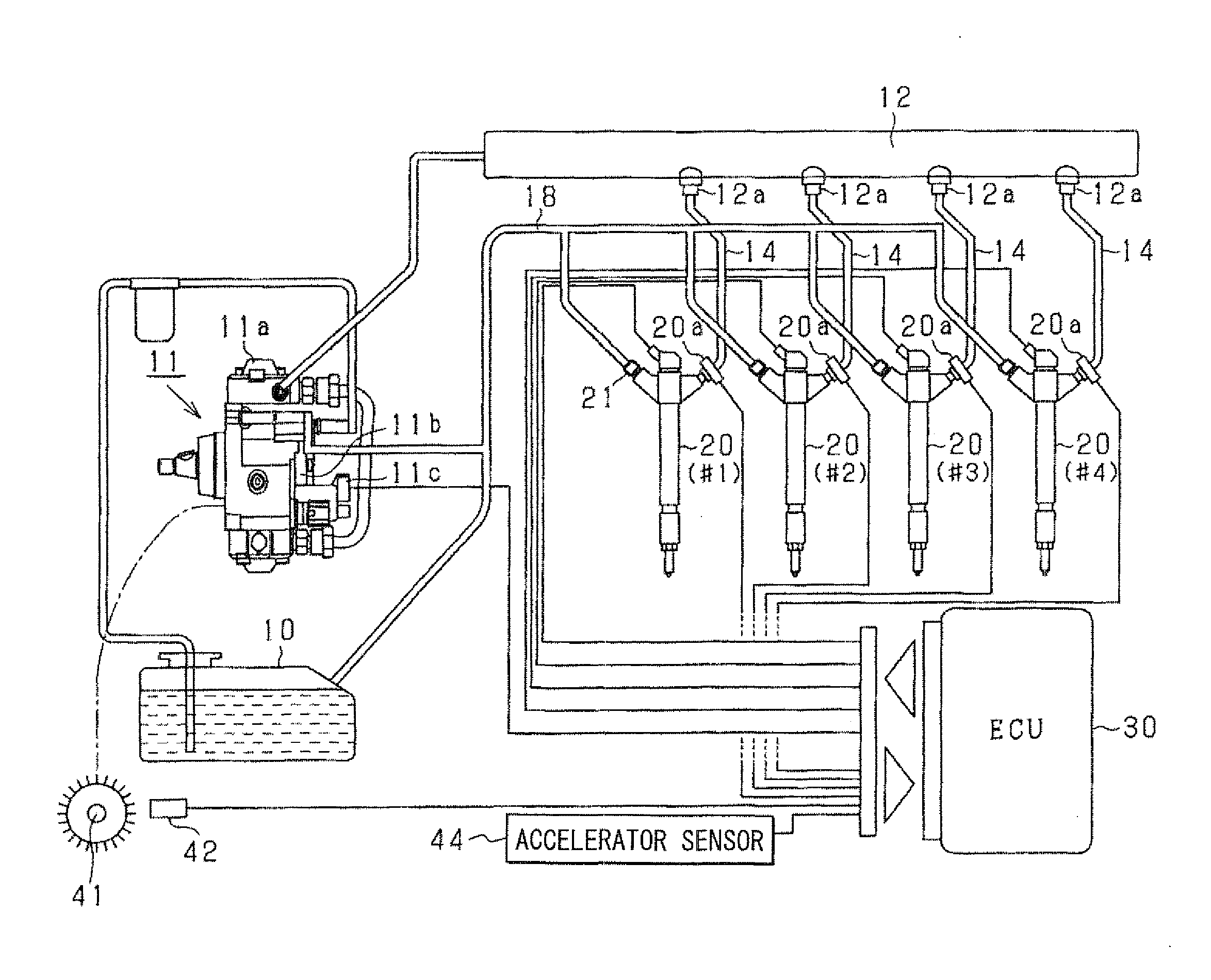
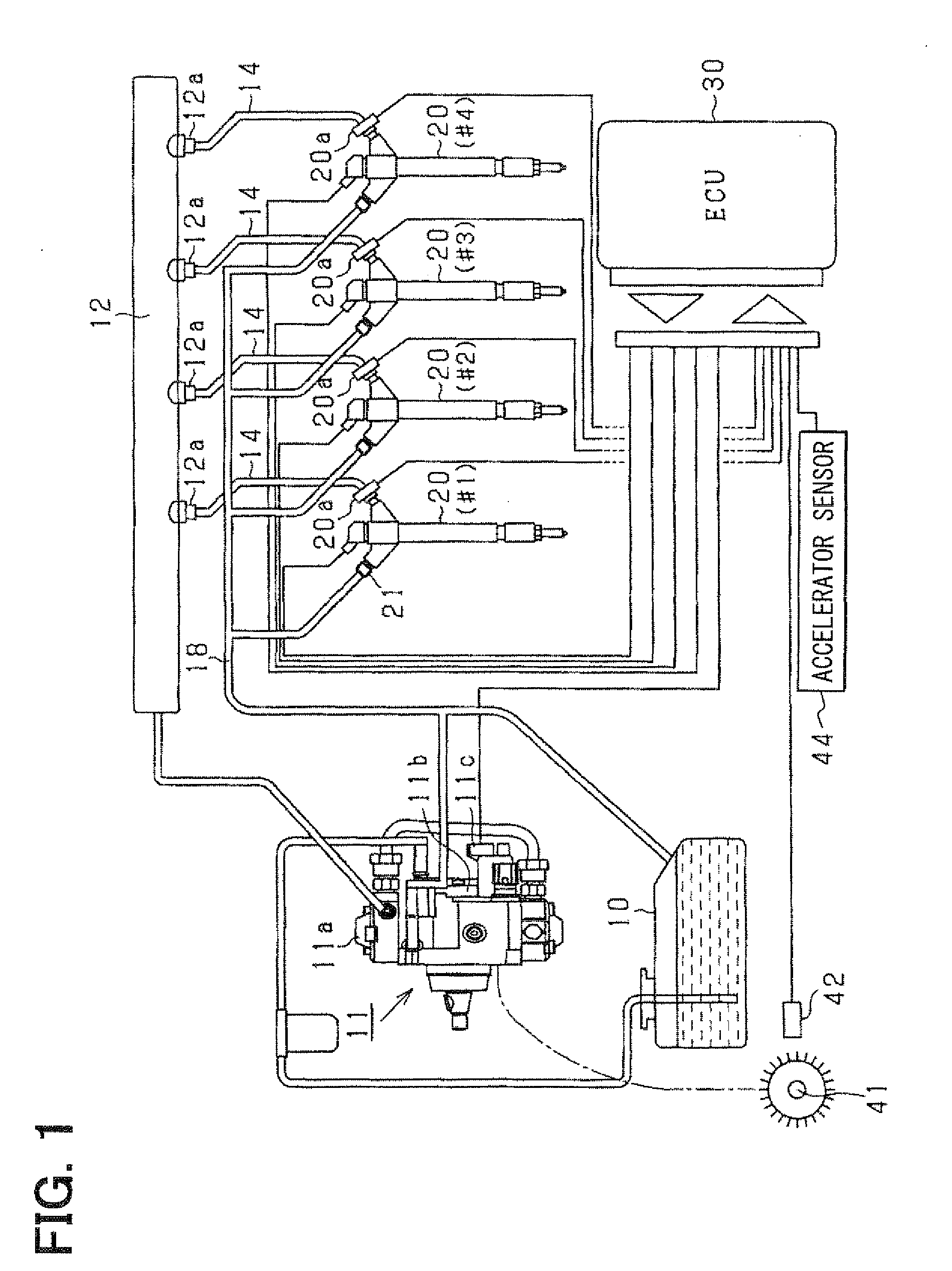
[0048]FIG. 1 is a construction diagram showing an outline of a common rail fuel injection system according to an embodiment of the present invention. An electronic control unit (ECU) 30 feedback controls a fuel pressure in a common rail 12 in such a manner as to agree with a target fuel pressure. The fuel pressure in the common rail 12 is detected by a fuel pressure sensor 20a and controlled by adjusting an electric current supplied to a suction control valve 11c. Further, based on the fuel pressure, a fuel injection quantity of each cylinder and an output of the engine are controlled.

[0049]The various devices constructing the fuel supply system include a fuel tank 10, a fuel pump...

second embodiment

[0161]In the above first embodiment, the tangent line at the timing “t2” is defined as the falling-modeling function f1(t), and the tangent line at the timing “t4” is defined as the rising-modeling function f2(t). In a second embodiment, as shown in FIG. 18, a straight line passing through specified two points P11a, P12a on the falling waveform A1 is defined as the falling-modeling function f1(t). Similarly, a straight line passing through specified two points P21a, P22a on the rising waveform A2 is defined as the rising-modeling function f2(t). An intersection pressure (Pint) and an intersection timing (tint) are computed, at which the straight lines expressed by the first and the rising-modeling function intersect to each other.

[0162]It should be noted that the specific two points “P11a”, “P12a” represent the detection pressure on the falling waveform A1 at timings “t21” and “t22” which are respectively before and after the timing “t2”. Similarly, the specific two points “P21a”, “...


PUM


Abstract

A fuel injection detecting device computes a maximum-fuel-injection-rate-reach timing and a fuel-injection-rate-decrease-start timing based on a falling waveform of the fuel pressure and a rising waveform of the fuel pressure. The falling waveform represents the fuel pressure detected by a fuel sensor during a period in which the fuel pressure increases due to a fuel injection rate decrease. The rising waveform represents the fuel pressure detected by the fuel sensor during a period in which the fuel pressure decreases due to a fuel injection rate increase. The rising waveform and the falling waveform are respectively modeled by modeling function. In a case of small fuel injection quantity, an intersection timing at which lines expressed by the modeling functions intersect with each other is defined as the maximum-fuel-injection-rate-reach timing and the fuel-injection-rate-decrease-start timing.

Description

CROSS-REFERENCE TO RELATED APPLICATION[0001]This application is based on Japanese Patent Application No. 2009-74283 filed on Mar. 25, 2009, the disclosure of which is incorporated herein by reference.FIELD OF THE INVENTION[0002]The present invention relates to a fuel injection detecting device which detects fuel injection condition.BACKGROUND OF THE INVENTION[0003]It is important to detect a fuel injection condition, such as a fuel-injection-start timing, a maximum-fuel-injection-rate-reach timing, a fuel injection quantity and the like in order to accurately control an output torque and an emission of an internal combustion engine. Conventionally, it is known that an actual fuel injection condition is detected by sensing a fuel pressure in a fuel injection system, which is varied due to a fuel injection. For example, JP-2008-144749A (US-2008-0228374A1) describes that an actual fuel-injection-start timing is detected by detecting a timing at which the fuel pressure in the fuel injec...

Claims


Application Information

Patent Timeline
IPC IPC(8): F02D41/30F02M63/00
CPCF02D41/3809F02D41/402F02D2041/2055F02D2250/04F02M47/027F02M63/0225F02D2200/0602
Inventor YAMADA, NAOYUKIISHIZUKA, KOJI
Owner DENSO CORP
Why Eureka
Try Eureka