Permanent-magnet synchronous motor

a permanent magnet, synchronous motor technology, applied in the direction of dynamo-electric machines, magnetic circuit rotating parts, magnetic circuit shapes/forms/construction, etc., can solve the problems of copper loss, coil ends, axial length increase of permanent magnet synchronous motors, etc., to achieve the effect of increasing efficiency

Inactive Publication Date: 2010-10-07
HITACHI LTD
View PDF9 Cites 12 Cited by
  • Summary
  • Abstract
  • Description
  • Claims
  • Application Information

AI Technical Summary

Benefits of technology

[0005]In the above prior art, however, a coil end is preset at each end in the rotational axis direction of the permanent-magnet synchronous motor, in which the stator is divided, so the number of coil ends is increased when compared with the number of coils ends before the division. Accordingly, there has been a problem in that the axial length of the permanent-magnet synchronous motor is increased. Furthermore, from the viewpoint of an insulation property, an air layer or the like needs to be provided between each two coil ends, further increasing the axial length. Another problem is that copper loss, which occurs at the coil ends, increases and thereby efficiency is lowered.
[0007]According to the present invention, it becomes possible to perform mechanical field weakening without having to increase the axial length of a permanent-magnet synchronous motor, and thereby the motor can be driven with counter electromotive force lowered in a high-speed area, so the need for a field weakening current is eliminated, increasing efficiency in the high-speed area.

Problems solved by technology

Accordingly, there has been a problem in that the axial length of the permanent-magnet synchronous motor is increased.
Another problem is that copper loss, which occurs at the coil ends, increases and thereby efficiency is lowered.

Method used


Image

  • Permanent-magnet synchronous motor
  • Permanent-magnet synchronous motor
  • Permanent-magnet synchronous motor

Examples


Embodiment Construction

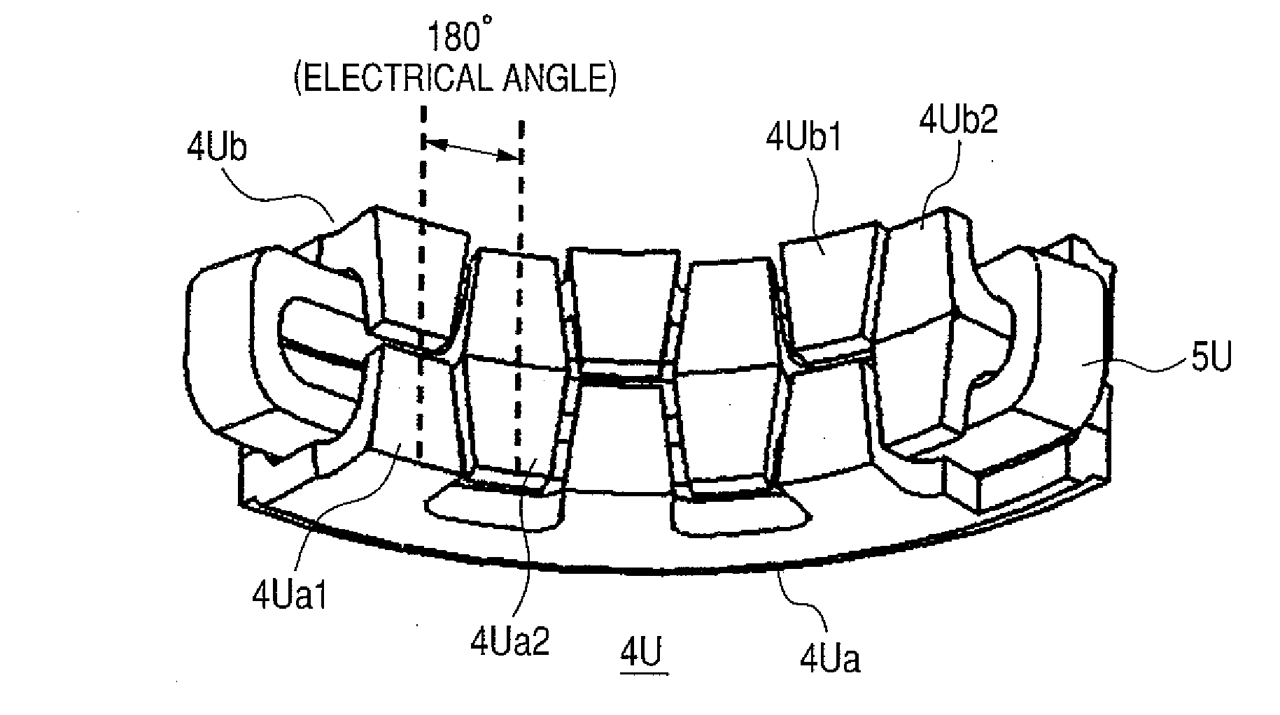
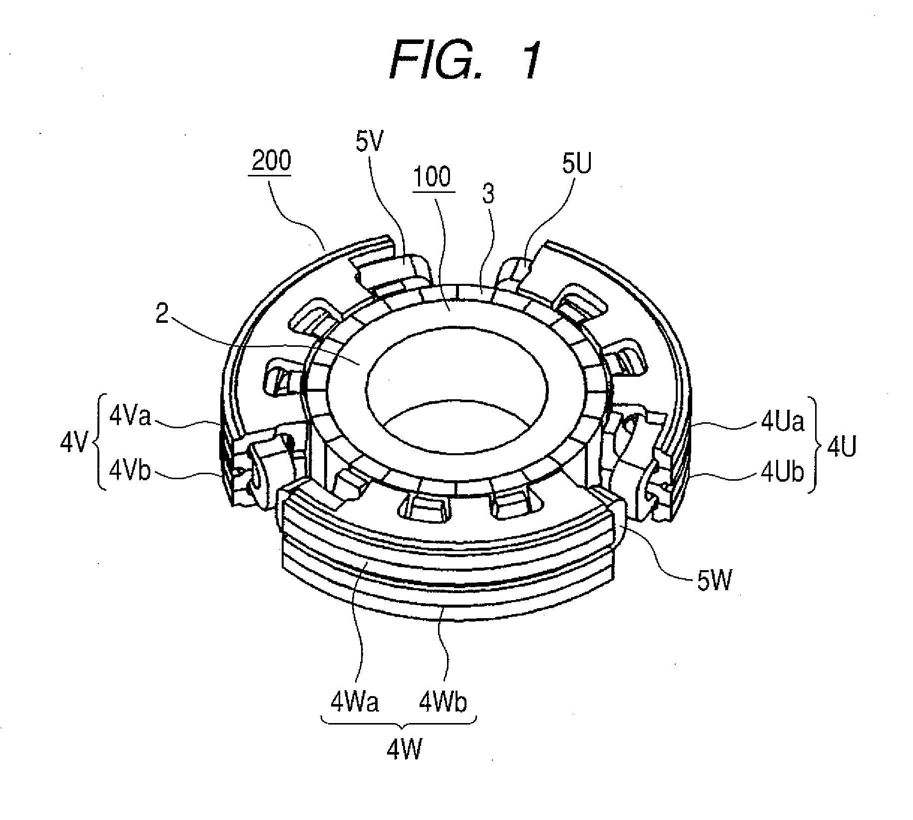
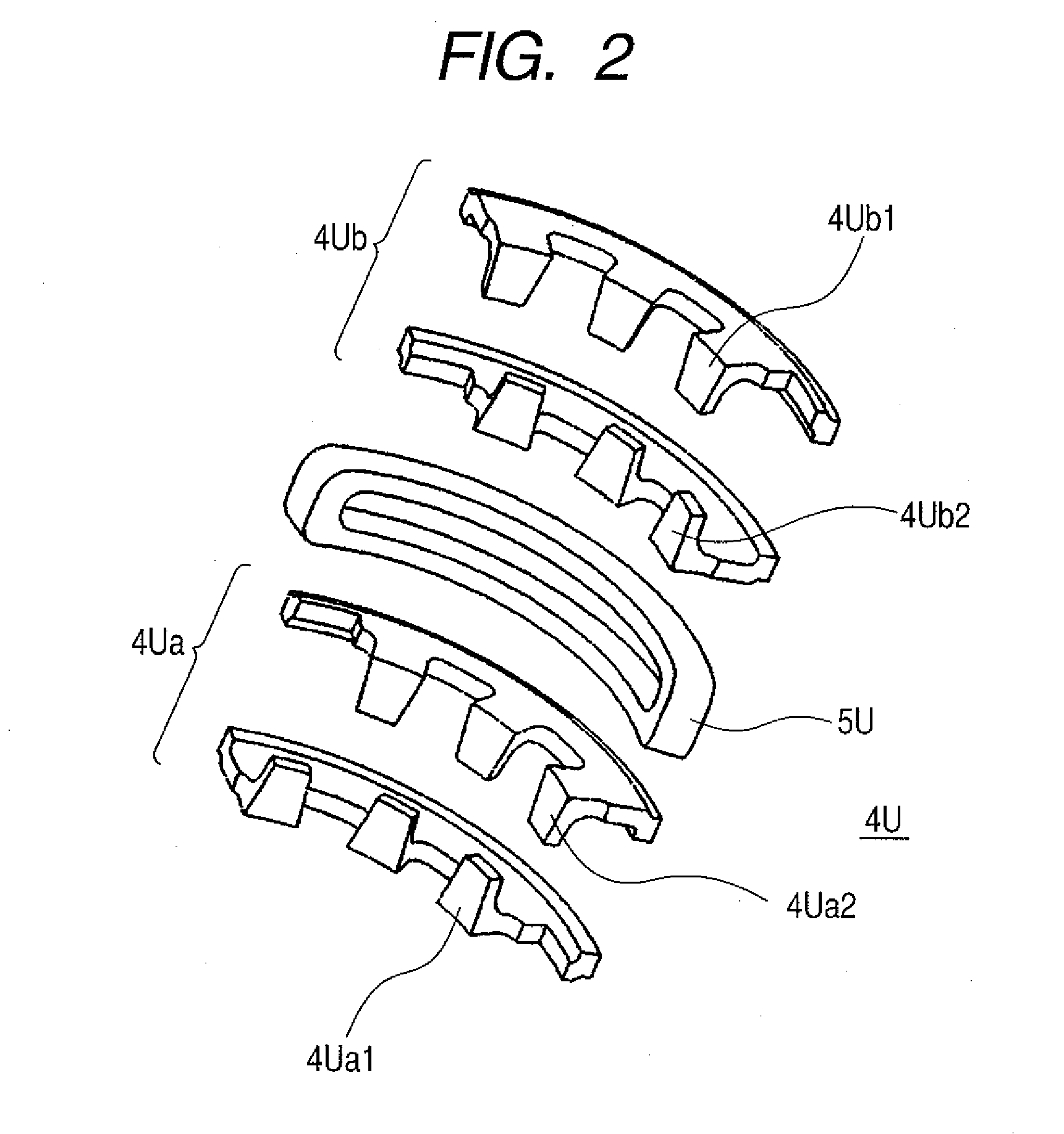
[0027]In a permanent-magnet synchronous motor having a stator in which a magnetic pole having an N pole and an S pole is formed in a circumferential direction with respect to a rotational axis, a rotor disposed on an inner diameter side of a yoke disposed in a radial direction of the stator, the rotor having permanent magnets placed in the circumferential direction with a slight spacing left between the rotor and the stator, and coils in a plurality of phases, which are disposed in the stator, the present invention is characterized in that the magnetic pole is divided into a plurality of magnetic poles in a direction perpendicular to the circumferential direction and placed, and a divided magnetic pole can be moved in the circumferential direction with respect to the rotational axis. In this case, the phases of the divided magnetic poles have a Phase difference.

[0028]Incidentally, the permanent-magnet synchronous motor according to the present invention is characterized in that the ...


PUM


Abstract

The present invention can achieve a highly efficient permanent-magnet synchronous motor that can obtain output in a high-speed area without prolonging the axis of the permanent-magnet synchronous motor.The present invention provides a highly efficient permanent-magnet synchronous motor that can obtain output in a high-speed area without prolonging the axis of the permanent-magnet synchronous motor, in which stator magnetic poles are formed by dividing a magnetic pole in each phase into a plurality of parts and placing them in a circumferential direction with respect to a rotational axis, at least one divided stator magnetic pole being made movable in the circumferential direction with respect to the rotational axis, and the phase of the movable stator is controlled.

Description

FIELD OF THE INVENTION[0001]The present invention relates to a permanent-magnet synchronous motor that is formed with a stator formed by a plurality of divided stator magnetic poles and with a rotor having permanent magnets.BACKGROUND OF THE INVENTION[0002]Since, in a conventional permanent-magnet synchronous motor, counter electromotive force by a magnet increases as the number of revolutions increases, if a power source is a battery or the like, driving in a high rotational speed area has been difficult due to a limitation of a power supply voltage. As a driving method by which a permanent-magnet synchronous motor is driven in a high rotational speed area, there is field weakening control in which a magnetic flux is equivalently weakened by a current. Since a current that does not contribute torque must have flowed, however, efficiency has been lowered.[0003]As a method that solves these problems, Patent Document 1 discloses a method in which mechanical field weakening is performe...

Claims


Application Information

Patent Timeline
Patent Type & Authority Applications(United States)
IPC IPC(8): H02K1/18H02K1/12
CPCH02K1/14H02K1/141H02K21/16H02K21/14H02K21/145H02K1/145
Inventor KOYAMA, TAKAYUKIKANAZAWA, HIROSHIKAWAMATA, SHOICHI
Owner HITACHI LTD
Why Eureka
Try Eureka