

Liquid crystal display device
a liquid crystal display and display device technology, applied in non-linear optics, instruments, optics, etc., can solve the problems of reducing the contrast ratio of the transmission display, reducing and obscuring the light passing through. , to achieve the effect of wide viewing angle, high contrast display, and significant reduction of the area of the /4 retarder in the transmission region
- Summary
- Abstract
- Description
- Claims
- Application Information
AI Technical Summary
Benefits of technology
Problems solved by technology
Method used
Image

Examples
embodiment 1
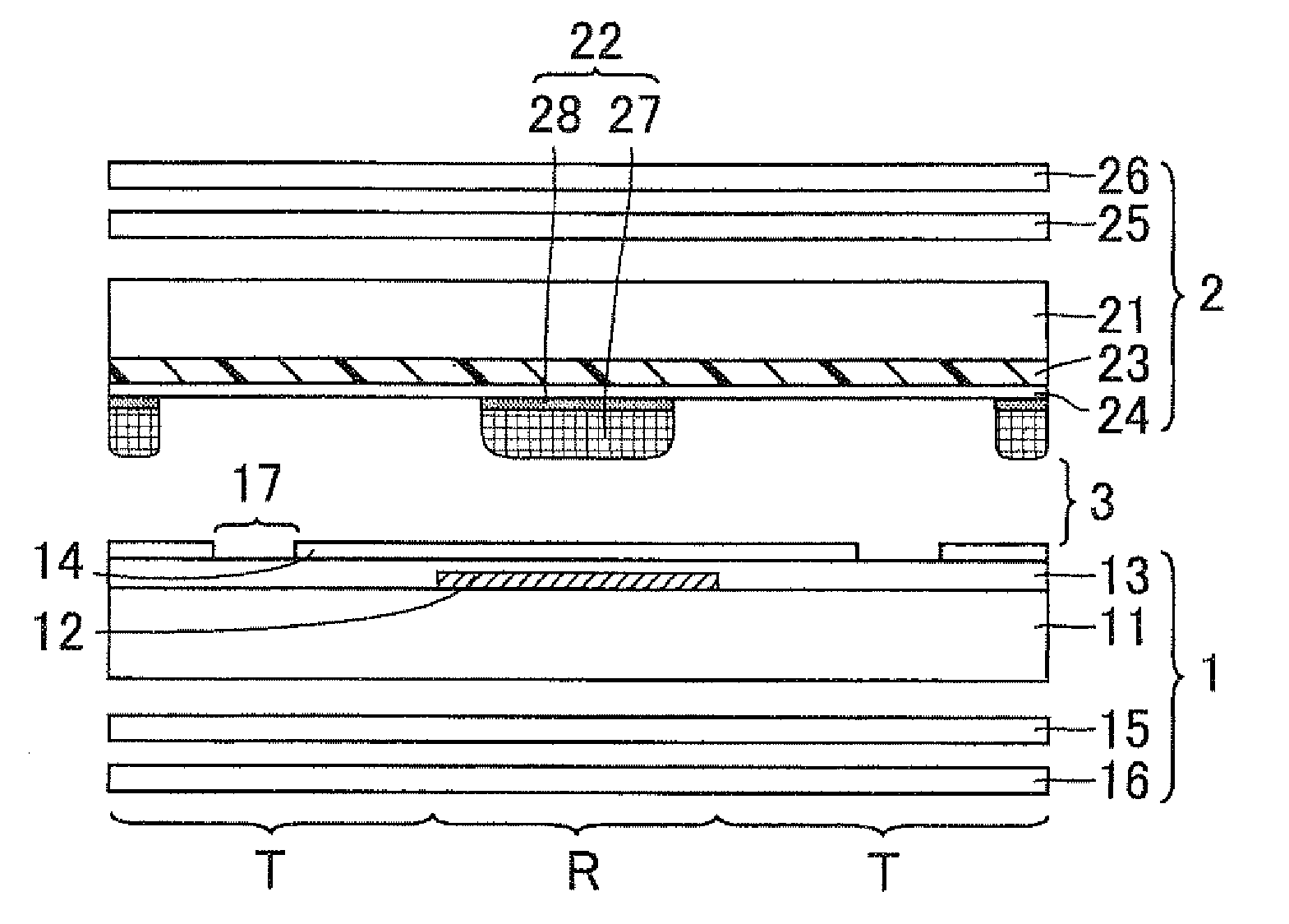
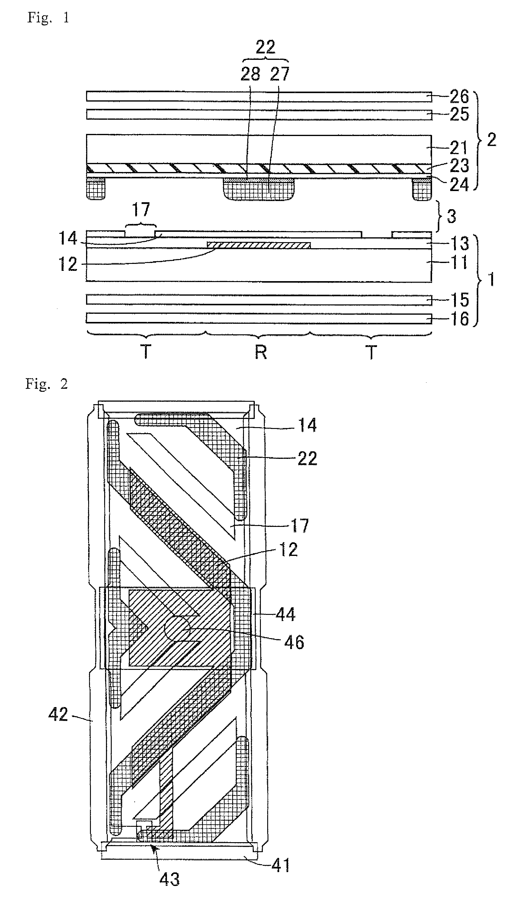
[0042]FIG. 1 is a cross-sectional view schematically showing a configuration of an LCD device in accordance with Embodiment 1. As shown in FIG. 1, the LCD device of Embodiment 1 is so configured that a first substrate 1 and a second substrate 2 are arranged with a LC layer 3 therebetween. In Embodiment 1, the second substrate 2 is a display face side substrate and the first substrate 1 is a back face side substrate. Further, the first substrate 1 is an active matrix substrate and the second substrate 2 is a color filter substrate. Specifically, the LCD device of Embodiment 1 includes the first substrate 1, the LC layer 3, and the second substrate 2 in this order toward the display face.
[0043]The LCD device of Embodiment 1 is a transflective LCD device including a reflector 12 partly arranged and a backlight as a light source. This allows the LCD device of Embodiment 1 to provide transmission display using transmission light from the backlight as display light and reflection display ...
embodiment 2
[0062]FIG. 4 is a cross-sectional view schematically showing a configuration of an LCD device of Embodiment 2. The LCD device of Embodiment 2 has the same configuration as in Embodiment 1, except that the rib 22 further includes a top portion 29 made of novolac resin on the LC layer 31 side surface, in addition to the alignment film 48 and the λ / 4 layer 47. The novolac resin is a material commonly used for the rib 22. This top portion 29 allows suppression of charge-up of DC potential upon voltage application, and image sticking phenomenon can be suppressed. However, the same effects as in Embodiment 1 are virtually obtained. The reason of this is as follows. In Embodiment 2, the rib 22 is arranged to overlap with the reflector 12, and so image sticking phenomenon in transmission display is hardly observed. Also in reflection display, it is hardly observed because the contrast ratio is about 1 / 100 of that in transmission display.
embodiment 3
[0063]FIG. 5 is a cross-sectional view schematically showing a configuration of an LCD device of Embodiment 3. The LCD device of Embodiment 3 is the same as in Embodiment 1, except that the LCD device includes no λ / 2 retarder. According to the present invention, the rib 22 is mainly arranged in the reflection region R, and so coloring caused by wavelength dispersion caused by the λ / 4 retarder in the rib 22 less occurs. In such a case, an embodiment no λ / 2 retarder is arranged may be employed.
PUM
| Property | Measurement | Unit |
|---|---|---|
| width | aaaaa | aaaaa |
| transmittance | aaaaa | aaaaa |
| reflectance | aaaaa | aaaaa |
Abstract
Description
Claims
Application Information