Data signal phase reversal correction method and system implementing the same

a data signal and correction method technology, applied in the field of psk (phase shift keying) modulated navigation data processing, can solve problems such as phase ambiguity errors, data frame corruption, and inability to correct data phase reversal

Active Publication Date: 2010-10-07
MEDIATEK INC
View PDF48 Cites 17 Cited by
  • Summary
  • Abstract
  • Description
  • Claims
  • Application Information

AI Technical Summary

Problems solved by technology

That is, it can track the carrier phase but with a possible error of
If a cycle slip occurs during the PLL operation, there might be a phase ambiguity error after the PLL locks the signal again.
Therefore, it can not correct the data phase reversal when the signal strength is so weak that the preamble length is not enough to detect the phase reversal.
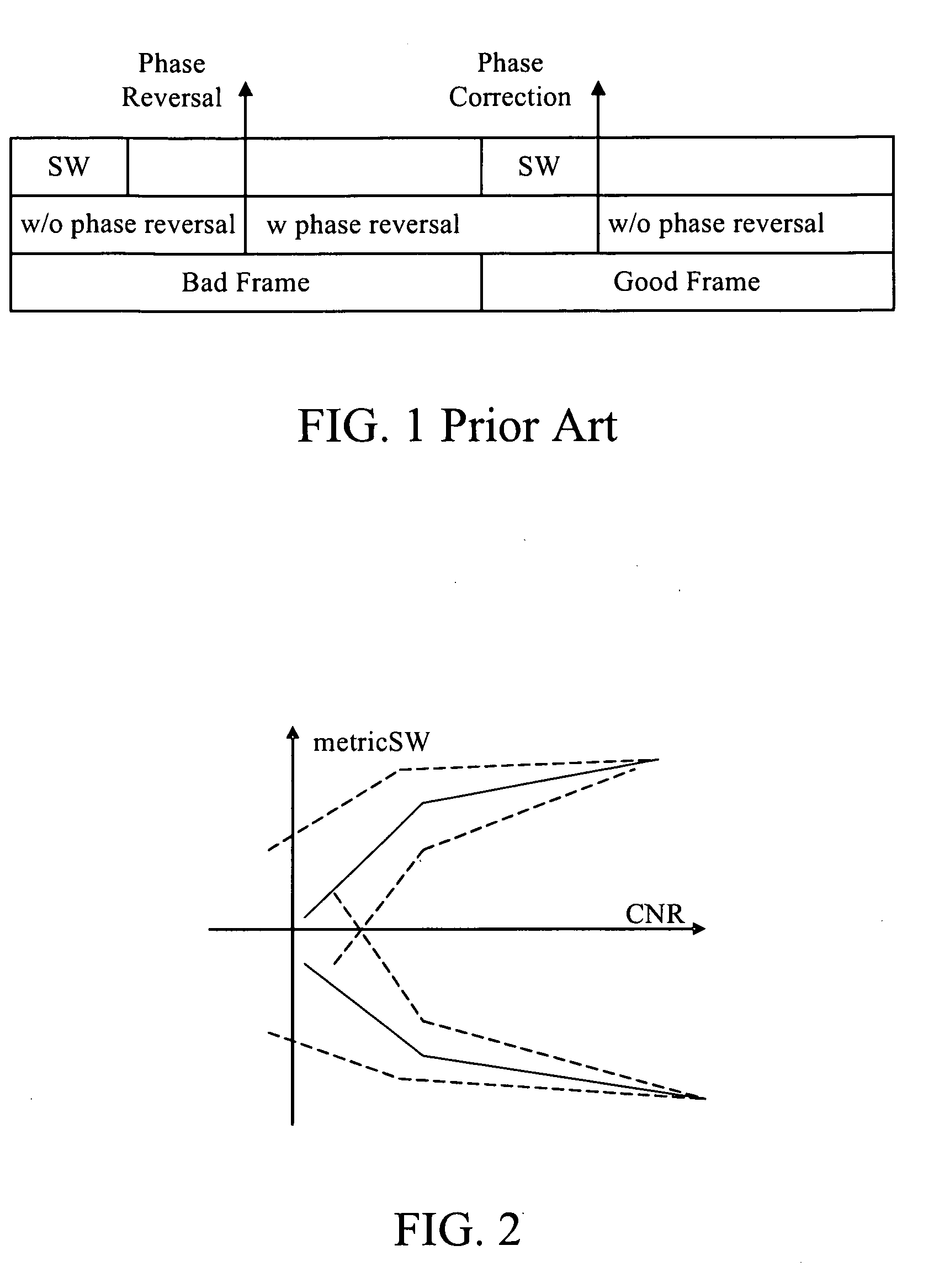
Moreover, a data frame is corrupted when a phase reversal occurs during its transmission.
This means that it is often not possible to quickly correct the phase reversal error by using the preamble and therefore results in corrupted frames.
This might be a problem for high dynamic and weak signal.
Note that there are possibly phase reversal errors in both PLL and FLL based data detection.
However, the PLL tracking robustness is weaker than FLL.
However, a DD error will propag

Method used


Image

  • Data signal phase reversal correction method and system implementing the same
  • Data signal phase reversal correction method and system implementing the same
  • Data signal phase reversal correction method and system implementing the same

Examples


first embodiment

[0037]FIG. 9 is a flowchart showing the data signal phase reversal correction method in accordance with the present invention. This method is substantially executed in the phase reversal detecting device 740 of FIG. 8. The process of this method starts at step S810. In step S820, the phase reversal detecting device 740 receives the data symbol stream symB. In step S830, the phase reversal detecting device 740 checks a flag phaseReversal, which indicates whether there is a phase reversal. The flag is initially set as false. At this time, since the pilot symbol stream has not been checked yet, the flag phaseReversal is false. Under such a condition, the process goes to step S850. In step S850, the phase reversal detecting device 740 computes a metricPT value as follows:

metricPT=∑i=0N-1NH(i)·symC(i)(2)

Where symC(i) is the pilot symbol stream of the received pilot signal, NH(i) is the corresponding symbols of a known sequence for the pilot signal (i.e. known pilot sequence), and metricP...

second embodiment

[0040]FIG. 11 is a flowchart showing the data signal phase reversal correction method in accordance with the present invention. The process starts at step S1010. In step S1020, the data symbol stream symB is received. In step S1025, metricSW is computed by using equation 1. In parallel, the pilot symbol stream symC is received in step S1040 and metricPT is computed by using equation 2. In step S1060, the phase reversal detecting device 740 decides the state of the flag phaseReversal (true or false) based on both metricSW and metricPT. Other timing information such as the time corresponding relationship between the computed metricPT and metricSW can also be brought into consideration. If there is a phase reversal, the flag phaseReversal is set as true; otherwise the flag phaseReversal is set as false. In step S1070, the flag phaseReversal is checked. If the flag is false, the process goes back to step S1020. If the flag is true, it means that there is a phase reversal, then the phase...


PUM


Abstract

A data signal phase reversal correction method and system implementing the same are disclosed. In the present invention, a pilot signal of a satellite is checked to see if there is a phase reversal according to an accumulation of correction results of symbols of the received pilot signal with corresponding symbols of a known pilot sequence. It is determined whether a phase correction of a data signal of the satellite is to be executed or not by referencing the phase reversal determination result of the pilot signal.

Description

TECHNICAL FIELD OF THE INVENTION[0001]The present invention relates to PSK (Phase Shift Keying) modulated navigation data processing in GNSS (Global Navigation Satellite System), more particularly, to a method for correcting a phase reversal of a data signal of PSK modulated navigation data, and a receiver implementing such a method.BACKGROUND OF THE INVENTION[0002]For PSK (Phase Shift Keying) communication system, the carrier phase is modulated by the transmitted data. Taking BPSK (Binary PSK) for example, the carrier phase is reversed (added 180 degrees) when a data symbol 0 is transmitted. On the other hand, the carrier phase is not changed when a data symbol 1 is transmitted. In general, the carrier phase is changed according to the transmitted data symbol. For a MPSK (Multiple PSK) modulation, where M is equal to 2 (BPSK), 4(QPSK) and so on, the carrier phase will stay in one of the M states:0,360M,360×2M,…,360×(M-1)Mdegrees, when a data symbol is transmitted. The received carr...

Claims


Application Information

Patent Timeline
IPC IPC(8): H04L27/22
CPCG01S19/24H04B1/7075H04B2201/70701H04B2201/70715H04L2027/0087H04L27/0014H04L2027/003H04L2027/0067H04L7/042
Inventor CHEN, KUN-TSO
Owner MEDIATEK INC
Why Eureka
Try Eureka