Apparatus for moving tunnel part of boarding bridge

Active Publication Date: 2010-10-14
OTIS ELEVATOR CO
View PDF13 Cites 0 Cited by
  • Summary
  • Abstract
  • Description
  • Claims
  • Application Information

AI Technical Summary

Benefits of technology

[0014]One feature of the disclosed example is that it allows for moving a tunnel part of a boarding bridge in which the apparatus life can be further improved by preventing noise generation due to an instantaneous change in the connection state of a second tunnel part and a third tunnel part and the application of impact on the second tunnel part and the third tunnel part by a forced connection.
[0015]Another feature of the disclosed example is that it allows for moving a tunnel part of a boarding bridge in which the load applied to a lift column and a driving gear is further reduced and the movement of the second tunnel part and the third tunnel part can be more rapidly and smoothly realized when the third tunnel part moves the second tunnel part by transmitting pressure.

Problems solved by technology

But when the cable tray is applied to a tunnel divided into three or more sections, since the multiple tunnel parts are moved together and the tunnel is formed with a designated length, if the above-mentioned structure is simply applied to each tunnel part, the multiple connection cables are spread apart and bent together in the process of reciprocating movement of the multiple tunnel parts, so that their paths are likely to overlap, causing entanglements with each other.
Also, installing wiring cables and connection cables to supply power to the multiple tunnel parts along paths independent of each other to prevent entanglements makes the structure of the cable tray complicated due to the multiple wiring paths, and the volume and weight are increased proportionally, so that not only are material and manpower consumption large, but maintenance and control is difficult.

Method used


Image

  • Apparatus for moving tunnel part of boarding bridge
  • Apparatus for moving tunnel part of boarding bridge
  • Apparatus for moving tunnel part of boarding bridge

Examples


Embodiment Construction

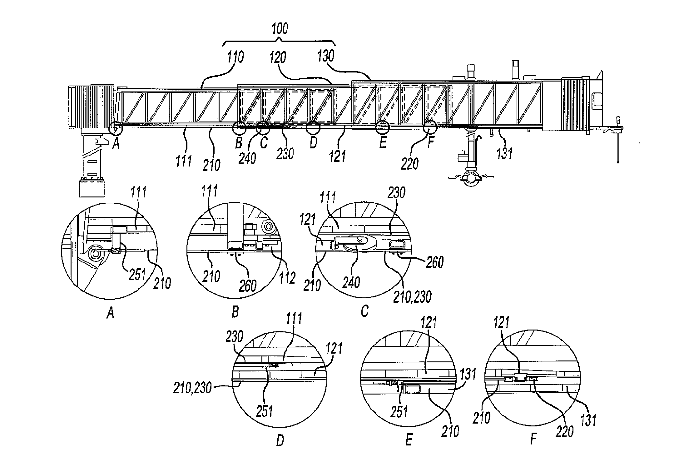
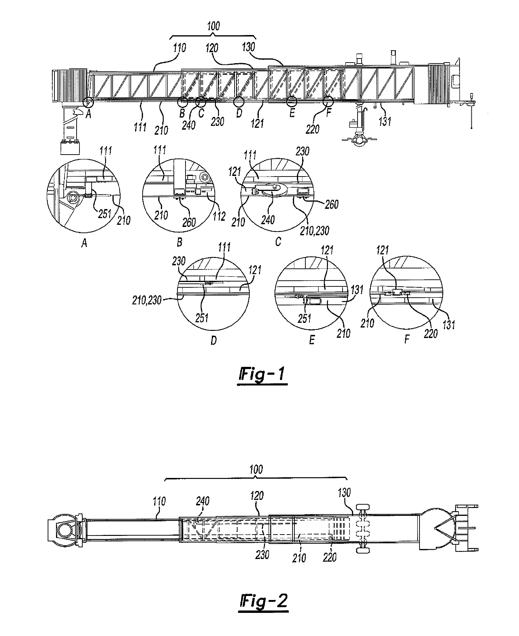
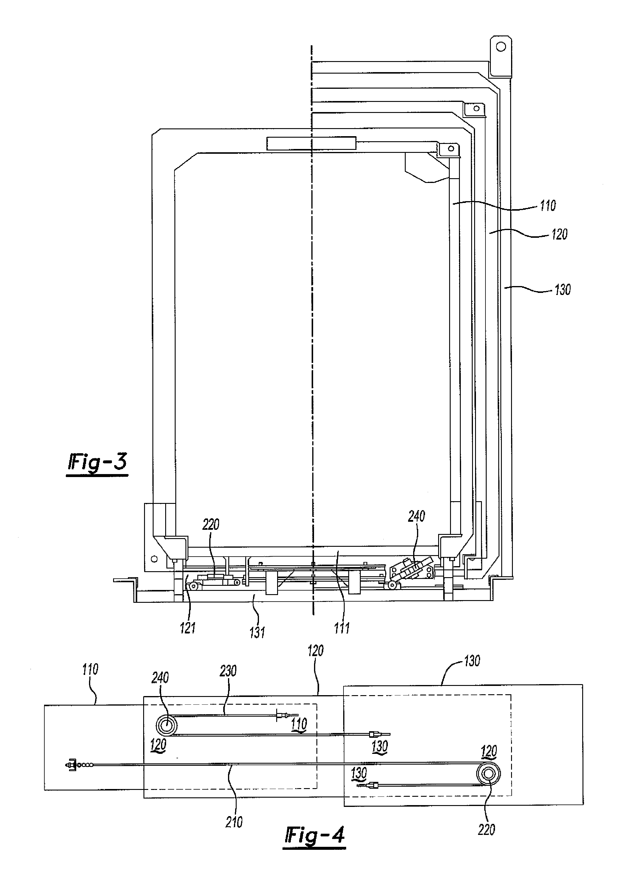
[0063]The apparatus for moving a tunnel part of a boarding bridge of the present invention, as shown in FIGS. 1-3, is a tunnel part moving apparatus that is mounted in a boarding bridge equipped with a tunnel (100) that consists of first tunnel part (110), second tunnel part (120), and third tunnel part (130) and can be interlocked and moved so that the above-mentioned second tunnel part (120) and third tunnel part (130) are placed in contact and connected to each other based on the above-mentioned first tunnel part (110). This apparatus has a structure constituted mainly by first rope (210), first pulley (220), second rope (230), and second pulley (240).

[0064]The above-mentioned first rope (210) and first pulley (220) are constitutional elements that are installed on the above-mentioned first, second, and third tunnel parts (110, 120, 130) so that when the above-mentioned third tunnel part (130) is moved to the above-mentioned first tunnel part (110), the above-mentioned second tun...


PUM


Abstract

An exemplary apparatus is for moving a tunnel part of a boarding bridge equipped with a tunnel (100) that consists of a first tunnel part (110), a second tunnel part (120), and a third tunnel part (130) in sequence from one side and can be moved so that the second tunnel part (120) and third tunnel part (130) are placed in contact and are connected to each other based on the first tunnel part (110). The apparatus includes a first rope (210) with one end coupled with the first tunnel part (110) and its other end coupled with the third tunnel part (130). A first pulley (220) that fixedly coupled to the second tunnel part (120) by hooking the first rope (210) at a position that is separated toward the other end side rather than both ends of the first rope (210) and is interlocked and moved in accordance with the moving displacement of the other end of the first rope (210). A second rope (230) is installed separately from the first rope (210) with one end coupled with the first tunnel part (110) and its other end coupled with the third tunnel part (130). A second pulley (240) is fixedly coupled to the second tunnel part (120) by hooking the second rope (230) at a position that is separated toward one end side rather than both ends of the second rope (230) and is interlocked and moved in accordance with the moving displacement of the other end of the second rope (230).

Description

TECHNICAL FIELD[0001]The present invention pertains to an apparatus for moving a tunnel part of a boarding bridge. More specifically, the present invention pertains to an apparatus for moving a tunnel part of a boarding bridge that is coupled with a tunnel equipped with multiple tunnel parts, which can be placed in contact and connected to each other on a boarding bridge that is installed so that passengers can move conveniently between an airport building and an airplane, and stably moves the multiple tunnel parts.DESCRIPTION OF THE RELATED ART[0002]Boarding bridges are installed between an airport building and airplanes in an airport, provide passages in which passengers can move safely and conveniently from the airport building to the airplanes without being influenced by various weather conditions or the external environment, and have a structure in which the length can be expanded and contracted and the direction can be changed in accordance with the distance between the airpor...

Claims


Application Information

Patent Timeline
IPC IPC(8): B64F1/305B66D1/26F16L3/02
CPCB64F1/305
Inventor KIM, JU RYONG
Owner OTIS ELEVATOR CO
Why Eureka
Try Eureka