
Cone penetrometers for measuring impedance of ground

Inactive Publication Date: 2010-10-14
KOREA UNIV IND & ACADEMIC CALLABORATION FOUND
View PDF5 Cites 19 Cited by
  • Summary
  • Abstract
  • Description
  • Claims
  • Application Information

AI Technical Summary

Benefits of technology

[0017]It is, therefore, a first object of the present invention to provide a cone penetrometer that is designed to measure the impedance of the ground at a tip portion thereof to improve the accuracy and reliability of the measured results, as well as that can be miniaturized while maintaining high stiffness against buckling.
[0018]It is a second object of the present invention to provide a cone penetrometer that is designed to measure the impedance of the ground at a tip portion thereof and use an optical fiber sensor to improve the accuracy and reliability of the measured results, as well as that can be miniaturized while maintaining high stiffness against buckling.
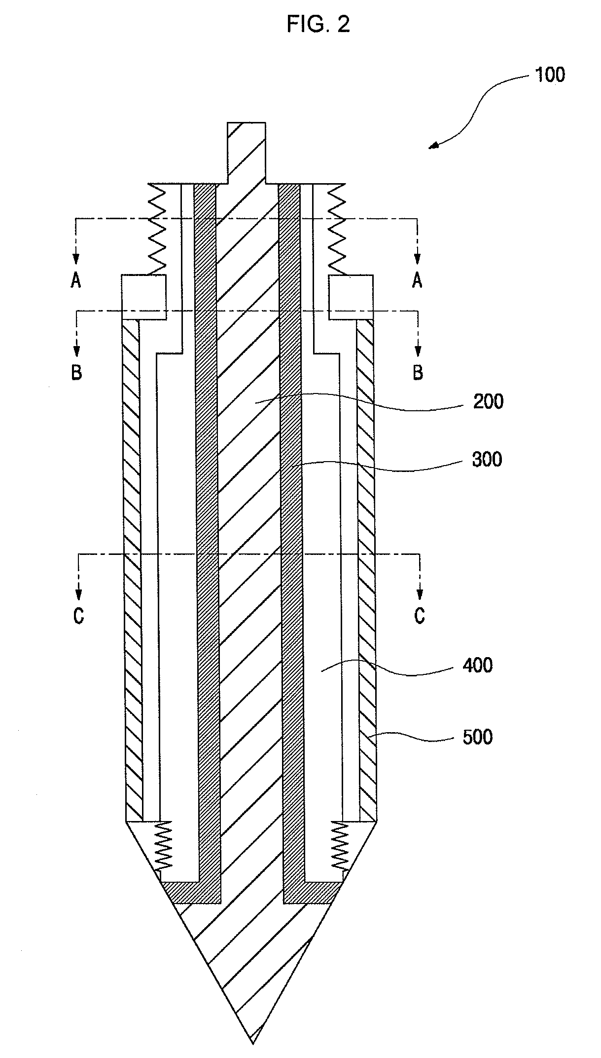
[0019]In order to accomplish the first object of the present invention, there is provided a cone penetrometer for measuring the impedance of the ground, comprising: an inner electrode including a cone, a first contact portion to which terminal cables of an impedance meter are connected, and a metal rod, whose diameter is smaller than that of the cone, having a front end connected to the bottom of the cone and a rear end connected to the first contact portion; an outer electrode, whose inner diameter is smaller than the diameter of the cone, in the form of a hollow tube accommodating the metal rod; an insulator layer formed between the inner electrode and the outer electrode to prevent short circuits between the two electrodes; and a penetrating rod in the form of a hollow tube accommodating the outer electrode.
[0021]In an embodiment, the rear end portion of the outer electrode includes coupling means to which an additional rod is coupled to increase the penetration depth of the cone penetrometer.
[0032]In order to accomplish the second object of the present invention, there is provided a cone penetrometer for measuring the impedance of the ground, comprising: an inner electrode including a cone, a hollow metal tube, whose outer diameter is smaller than the diameter of the cone, having a front end connected to and closed by the bottom of the cone and an open rear end, and a first contact portion which extends from the open rear end of the metal tube and to which terminal cables of an impedance meter are connected; an outer electrode, whose inner diameter is smaller than the diameter of the cone, in the form of a hollow tube accommodating the metal tube; an insulator layer formed between the inner electrode and the outer electrode to prevent short circuits between the two electrodes; and a penetrating rod in the form of a hollow tube accommodating the outer electrode.
[0036]In an embodiment, the rear end portion of the outer electrode includes coupling means to which an additional rod is coupled to increase the penetration depth of the cone penetrometer.

Problems solved by technology

This phenomenon is called ‘disturbance.’ The disturbance phenomenon causes shear deformation failure of the ground particles and decreases the strength of the original ground, making it difficult to accurately investigate the properties of the target ground.
However, the overall equipment is huge and inconvenient to transport, and further creates a great deal of economic burden.
However, electrical resistivity survey using a conventional standard cone penetrometer has a problem in that the large diameter of the cone penetrometer induces a disturbance of the ground, as previously explained.
This disturbance leads to poor sensitivity of the cone penetrometer, making it difficult to accurately assess the layered structure of the ground.
Another problem is that the electrical resistivity of the already disturbed region by the penetration of the cone tip is measured, resulting in low reliability.
However, it is difficult to subminiaturize the cone penetrometer due to the internal element.
Another problem is that the removal of some measuring sensors is required to subminiaturize the cone penetrometer, making it impossible to measure various properties of the ground.

Method used


Image

  • Cone penetrometers for measuring impedance of ground
  • Cone penetrometers for measuring impedance of ground
  • Cone penetrometers for measuring impedance of ground

Examples


Embodiment Construction

[0064]Preferred embodiments of the present invention will now be described in detail with reference to the accompanying drawings in order to clarify the aspects of the present invention. In describing the present invention, detailed descriptions of related known functions or configurations are omitted in order to avoid making the essential subject of the invention unclear. The terms used herein are defined taking into account their functions and may be varied according to users' and operators' intentions and work practices. Therefore, the terms should be defined based on the disclosure throughout the entire specification.

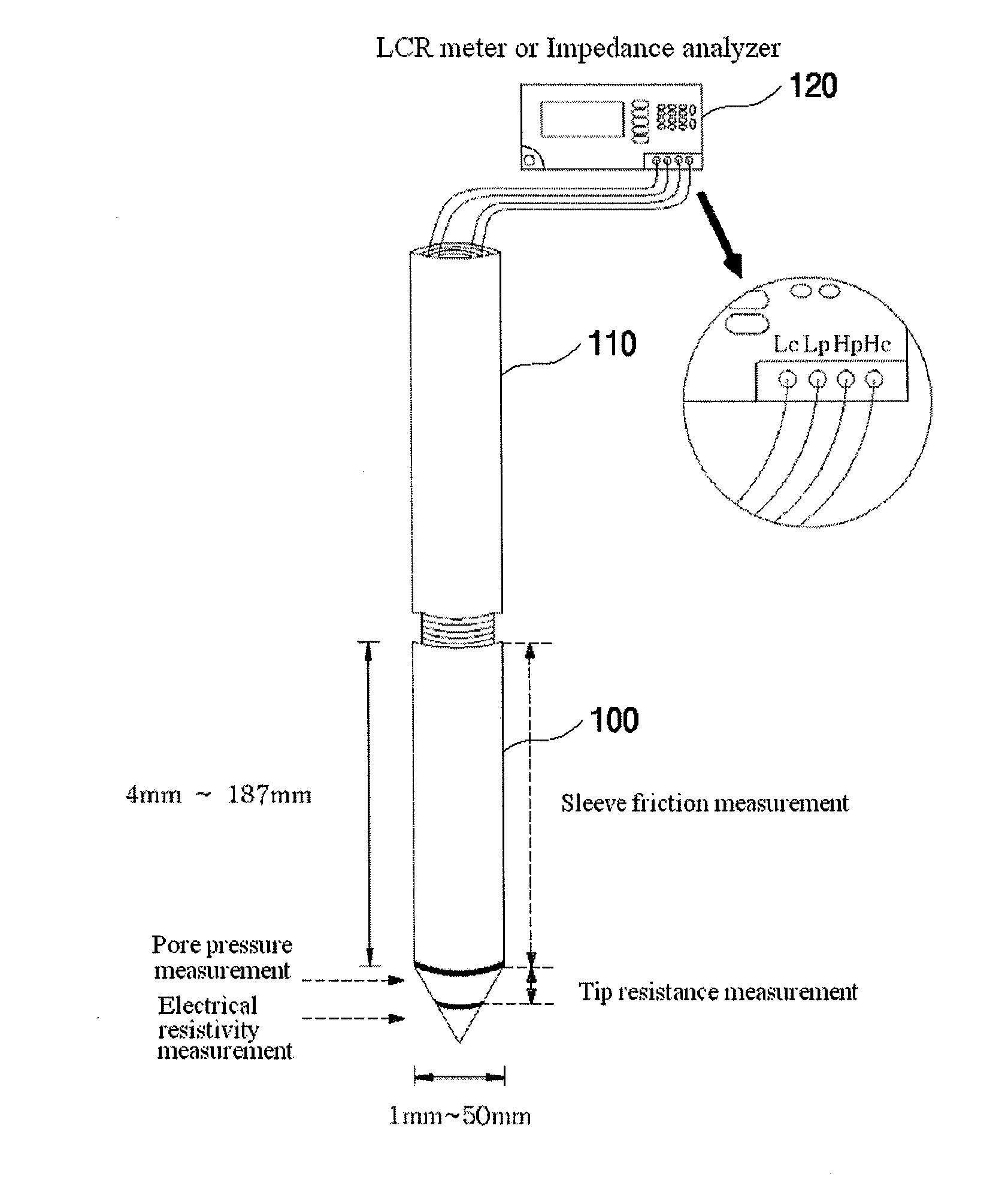
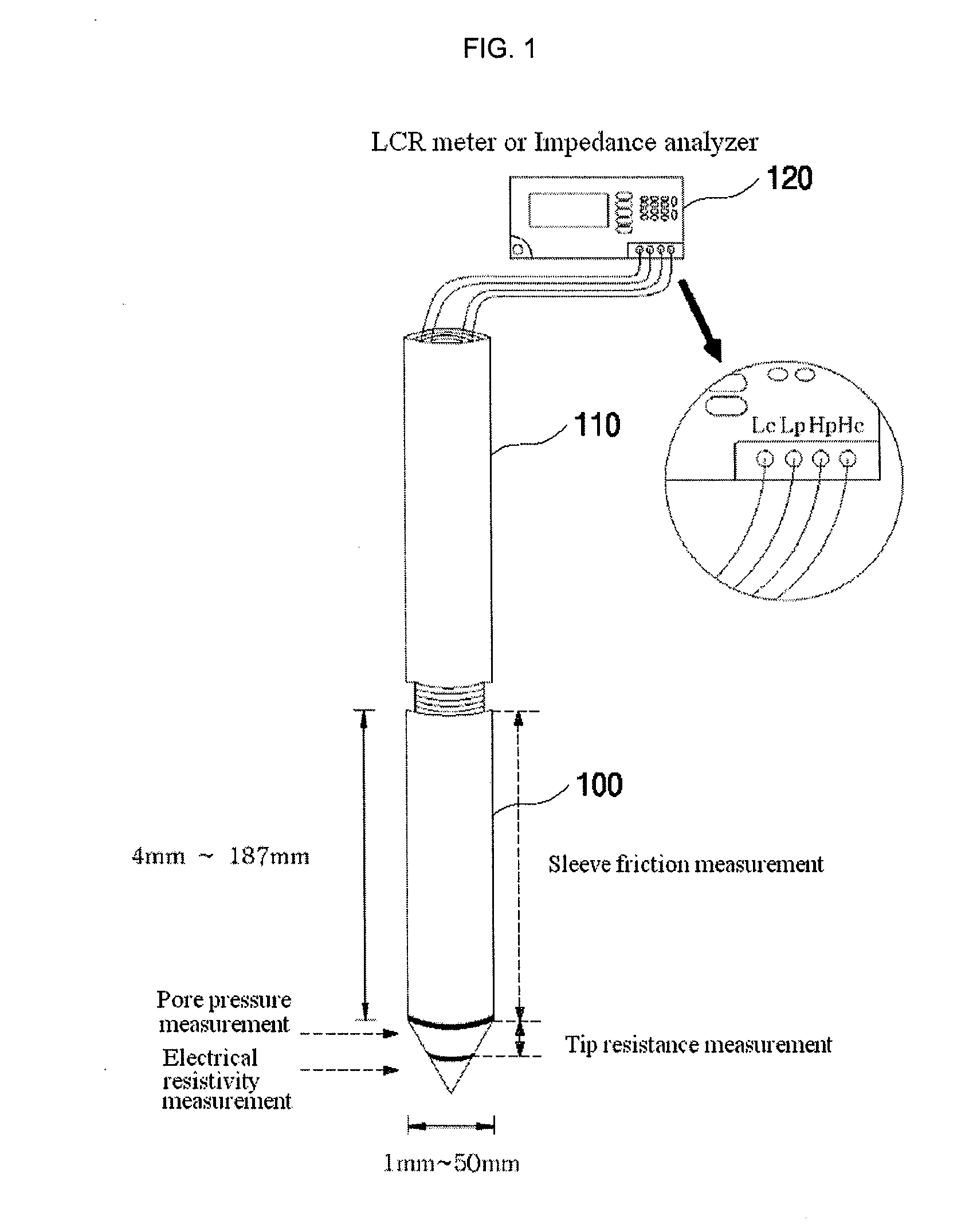
[0065]FIG. 1 is a view illustrating a cone penetrometer system according to an embodiment of the present invention.

[0066]Referring to FIG. 1, the cone penetrometer system comprises a cone penetrometer 100 for measuring the impedance of the ground, an additional rod 110 and an impedance meter 120.

[0067]The cone penetrometer 100 is designed to measure the impedance of...


PUM


Abstract

Provided are cone penetrometers for measuring the impedance of the ground. In an embodiment, the cone penetrometer comprises an inner electrode, an outer electrode, an insulator layer and a penetrating rod. The inner electrode includes a cone, a first contact portion to which terminal cables of an impedance meter are connected, and a metal rod. The metal rod has a diameter smaller than that of the cone. The metal rod has a front end connected to the bottom of the cone and a rear end connected to the first contact portion. The outer electrode has an inner diameter smaller than the diameter of the cone and is in the form of a hollow tube accommodating the metal rod. The insulator layer is formed between the inner electrode and the outer electrode to prevent short circuits between the two electrodes. The penetrating rod is in the form of a hollow tube accommodating the outer electrode. The use of the cone penetrometers improves the accuracy and reliability of the measured results. Further, the cone penetrometers can be miniaturized while maintaining high stiffness against buckling.

Description

CROSS REFERENCE TO RELATED APPLICATIONS[0001]This application claims priority to Korean Patent Application No. 10-2009-0031508, filed Apr. 10, 2009, and Korean Patent Application No. 10-2009-0086992, filed Sep. 15, 2009, both of which are incorporated herein by reference in their entirety.BACKGROUND OF THE INVENTION[0002]1. Field of the Invention[0003]The present invention relates to cone penetrometers for measuring the impedance of the ground, and more specifically to cone penetrometers that are designed to measure the impedance of the ground at a tip portion thereof to improve the accuracy and reliability of the measured results, as well as that can be miniaturized while maintaining high stiffness against buckling.[0004]2. Description of the Related Art[0005]Soft ground created as a result of a geographical process of erosion, weathering and deposition over many centuries has various characteristics and structures depending on the conditions where it has been created. Soft ground ...

Claims


Application Information

Patent Timeline
IPC IPC(8): G01N3/42
CPCE02D1/022
Inventor LEE, JONG-SUBYOON, HYUNG-KOOKIM, RAE HYUNKIM, JOON HAN
Owner KOREA UNIV IND & ACADEMIC CALLABORATION FOUND
Learn More