Fiber Optic Solar Nanogenerator Cells

Inactive Publication Date: 2010-10-14
GEORGIA TECH RES CORP
View PDF17 Cites 21 Cited by
  • Summary
  • Abstract
  • Description
  • Claims
  • Application Information

AI Technical Summary

Problems solved by technology

However, solar cells cannot produce electricity at times when there is insufficient ambient light, such as in the evening.
However, the power output of the nanogenerator was relatively low in some applications.
These concentrators are expensive and have therefore been limited in scalability.

Method used


Image

  • Fiber Optic Solar Nanogenerator Cells
  • Fiber Optic Solar Nanogenerator Cells
  • Fiber Optic Solar Nanogenerator Cells

Examples


Embodiment Construction

[0043]A preferred embodiment of the invention is now described in detail. Referring to the drawings, like numbers indicate like parts throughout the views. As used in the description herein and throughout the claims, the following terms take the meanings explicitly associated herein, unless the context clearly dictates otherwise: the meaning of “a,”“an,” and “the” includes plural reference, the meaning of “in” includes “in” and “on.”

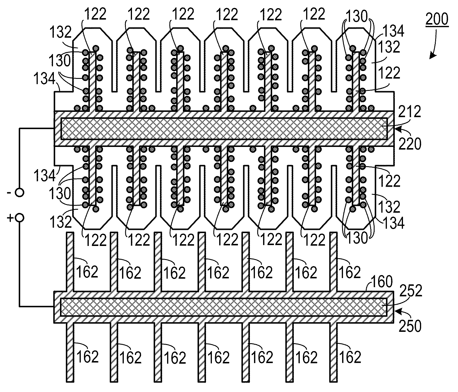
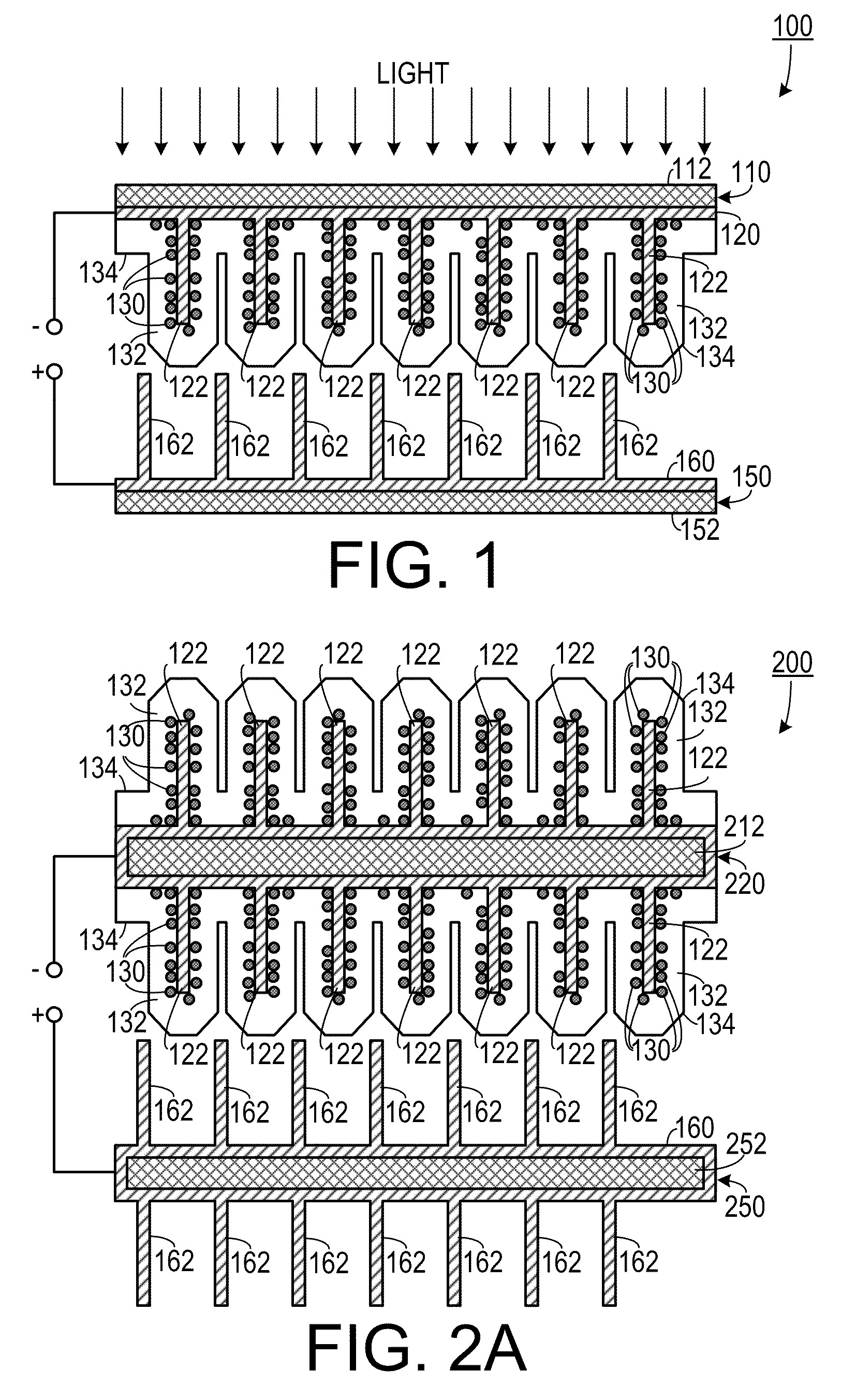
[0044]As shown in FIG. 1, one embodiment of a hybrid solar and mechanical power generator 100 includes a dye-sensitized solar power generating portion 110 that is electrically coupled to a first electrode 120. The solar power generating portion 110 includes a transparent substrate 112 (such as an ITO substrate) affixed to the first electrode 120. A plurality of semiconductor nanorods 122 (such as ZnO nanorods), also referred to as “nanowires,” extend from the first electrode. A light absorbing material having a predetermined optical absorption range is a...


PUM


Abstract

A solar cell employs an optical fiber and semiconductor nanowires grown around the fiber. A p-n junction based design, organic-inorganic heterojunction, or a dye-sensitized structure is built at the surfaces of the nanowires. Light entering the fiber from a tip propagates through the fiber until it enters a nanowire where it reaches a photovoltaic element. Light entering the fiber cannot escape until it interacts with a photovoltaic element, thereby increasing the solar conversion efficiency. The fiber can transmit light, while the nanowires around the fibers increase the surface area of light exposure.

Description

CROSS-REFERENCE TO RELATED APPLICATION(S)[0001]This application claims the benefit of: U.S. Provisional Patent Application Ser. No. 61164726, filed Mar. 30, 2009; U.S. Provisional Patent Application Ser. No. 61164730, filed Mar. 30, 2009; and U.S. Provisional Patent Application Ser. No. 61165096, filed Mar. 31, 2009; the entirety of each of which is hereby incorporated herein by reference.[0002]This application is a continuation-in-part of, and claims the benefit of, U.S. patent application Ser. No. 12194943, filed Aug. 20, 2008, which is a non-provisional of U.S. Provisional Patent Application Ser. No. 61051386, filed May 8, 2008, the entirety of each of which is hereby incorporated herein by reference.BACKGROUND OF THE INVENTION[0003]1. Field of the Invention[0004]The present invention relates to electric power generation systems and, more specifically, to a hybrid solar power and mechanical power generating system.[0005]2. Description of the Related Art[0006]There are generally t...

Claims


Application Information

Patent Timeline
IPC IPC(8): H01L31/052H01L31/0232
CPCH01G9/2086H01L27/304H01L31/0232H01L31/0547H01L31/03529Y02E10/52Y02E10/542H01L31/035281H10K30/53
Inventor WANG, ZHONG L.WEINTRAUB, BENJAMINWEI, YAGUANG
Owner GEORGIA TECH RES CORP
Why Eureka
Try Eureka