
Method and device

a technology of impulse generation and control device, which is applied in the direction of percussive tools, manufacturing tools, portable drilling machines, etc., can solve the problem that the available impact energy is not fully used

Inactive Publication Date: 2010-10-14
ATLAS COPCO ROCK DRILLS
View PDF2 Cites 6 Cited by
  • Summary
  • Abstract
  • Description
  • Claims
  • Application Information

AI Technical Summary

Benefits of technology

[0011]According to the present invention there is provided a method for controlling a rock drilling process, with an impulse-generating device comprising an impact element transmits a shock wave to a tool connected to the impact-generating device, where a portion of the energy of said shock wave is transmitted to the rock by means of the tool and a portion of the shock wave energy is reflected and returned to the impulse-generating device as reflected energy. The method comprises the steps of generating at least one parameter value that represents the reflected energy, and to control the interaction of the impact element with the tool at least partially based on said value or values to control the rise time of said shock wave and / or the length of said shock wave. This has the advantage that the form of the shock wave at all times can be controlled based on current conditions to thereby keep harmful reflection energies at an minimum, below a predetermined value, or at a value that has been determined in relation to other demands on the drilling process.
[0012]The amplitude of the shock wave can also be controlled. This has the advantage that even larger possibilities of optimum control of the rock drilling device is provided.
[0013]At least one damping pressure in at least one damping chamber may constitute a representative quantity of the reflected energy. Alternatively, the quantity may constitute the strain of one or more strain gauges. This has the advantage that the reflection can be read in a simple manner.
[0014]The value or values representing the reflected energy may be generated continuously, acyclic, with predetermined intervals and / or when generating each or certain shock waves. This has the advantage that current input parameters for the regulation may always be available.

Problems solved by technology

A problem with all the abovementioned impact-generating devices is that available impact energy is not fully made use of.

Method used


Image

  • Method and device
  • Method and device
  • Method and device

Examples


Embodiment Construction

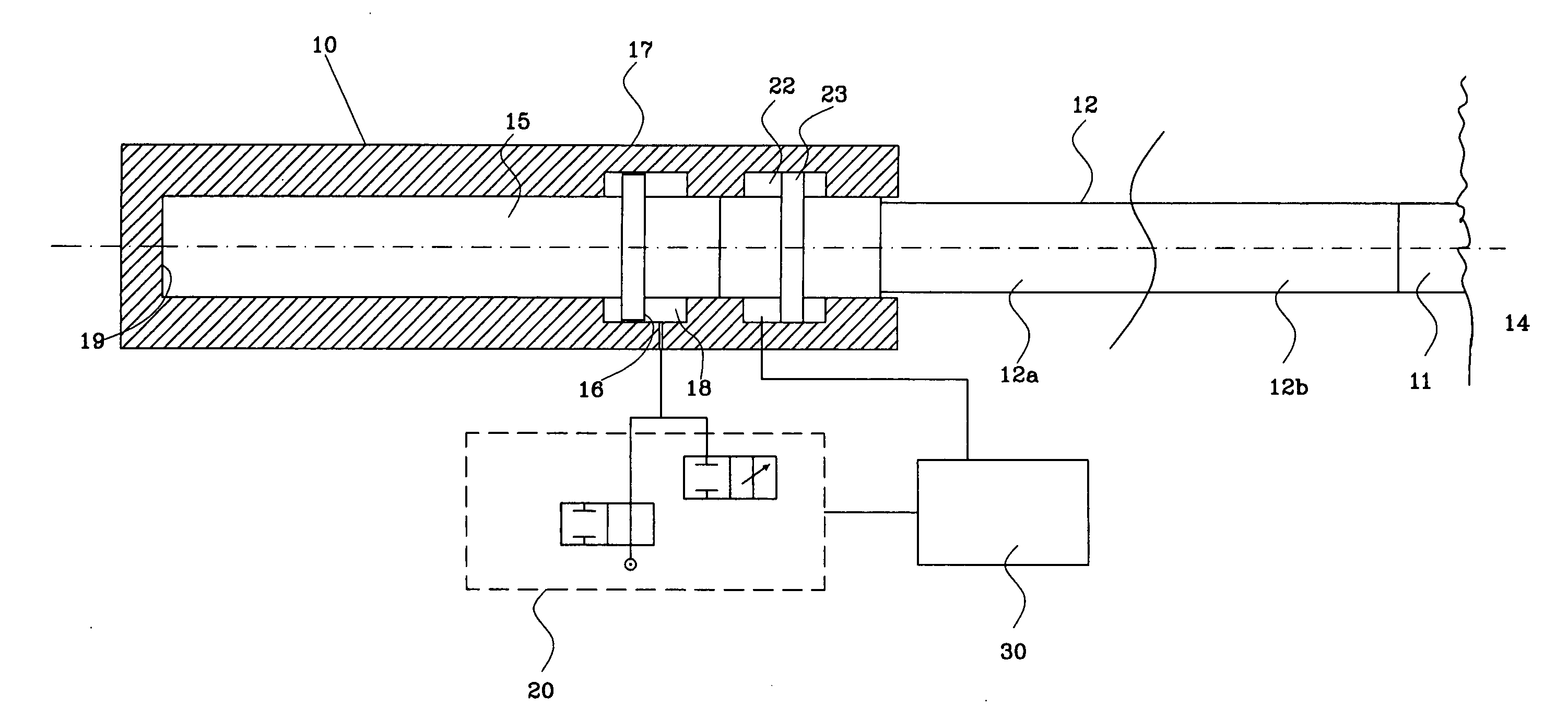
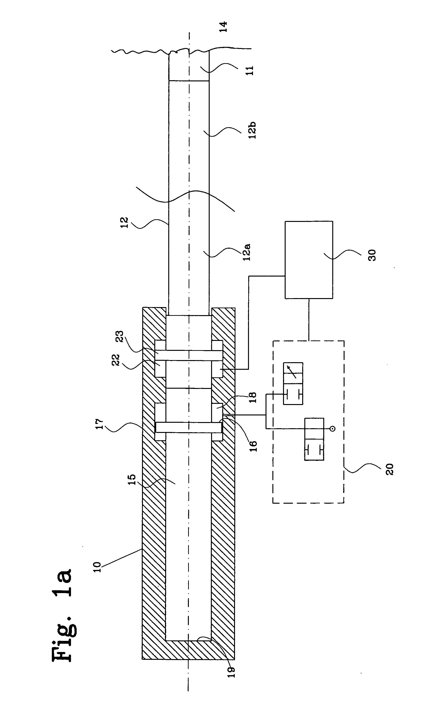
[0020]FIG. 1a shows an impulse-generating device 10 for a rock-drilling device that can advantageously be used with the present invention. During operation, the device 10 is connected to a drill tool such as a drill bit 11 via a drill string 12 consisting of one or more drill string components 12a, 12b. During drilling, energy in the form of shock waves is transferred to the drill string 12, and then from the drill string component 12a, 12b to drill string component 12a, 12b and finally to the rock 14 via the drill bit 11, for breaking the rock 14.

[0021]In the device 10 illustrated, a piston that moves forward and backward is not used to generate the shock waves, but instead a loaded impact element in the form of an impact piston 15 is used, which is urged towards the end of a housing 17 that is opposite to the drill string 12 by the effect of a pressure medium acting against a pressure area 16. During operation, a chamber 18 is pressurized via a control device 20 so that the pressu...


PUM

PropertyMeasurementUnit
energyaaaaaaaaaa
reflected energyaaaaaaaaaa
lengthaaaaaaaaaa

Abstract

The present invention relates to a method for controlling a rock drilling process, in which an impulse-generating device comprising an impact element transmits a shock wave to a tool connected to the impulse-generating device, whereby a portion of the energy of the shock wave is transmitted to the rock by means of the tool and a portion of the energy of the shock wave is reflected and brought back to the impulse-generating device as reflected energy. The method comprises steps of generating at least one parameter value representing the reflected energy, and regulating the interaction of said impact element with said tool at least partially based on said value or values to control the rise time and / or length of said shock wave. The invention also relates to a regulation device, an impulse-generating device and a drilling rig.

Description

FIELD OF THE INVENTION[0001]The present invention relates to a device and a method for Controlling an impulse-generating device for drilling in rock.BACKGROUND OF THE INVENTION[0002]In rock drilling, a drilling tool is used that is connected to a rock-drilling device via one or more drill string components. The drilling can be carried out in several ways, a common method being percussive drilling where an impulse-generating device, a striking tool, is used to generate impacts by means of an impact piston that moves forward and backward. The impact piston strikes the drill string, usually via a drill shank, in order to transfer impact pulses to the drilling tool via the drill string, and then on to the rock to deliver the energy of the shock wave. The impact piston is typically driven hydraulically or pneumatically, but can also be driven by other means, such as by electricity or some form of combustion.[0003]In another kind of impulse-generating devices the shock wave energy is gene...

Claims


Application Information

Patent Timeline
Patent Type & Authority Applications(United States)
IPC IPC(8): E21B1/24
CPCB25D17/245E21B1/02B25D2250/221E21B1/38E21B44/06
Inventor WEDDFELT, KENNETH
Owner ATLAS COPCO ROCK DRILLS
Learn More