HPLC schematic with integrated sample cleaning system

a cleaning system and liquid chromatography technology, applied in the field of high-performance liquid chromatography (hplc), can solve the problems of shortening the useful separation life of the sample cleaning system

Inactive Publication Date: 2010-10-14
SIELC TECH
View PDF13 Cites 60 Cited by
  • Summary
  • Abstract
  • Description
  • Claims
  • Application Information

AI Technical Summary

Benefits of technology

[0004]A basic object of this invention is to provide in an HPLC flow arrangement having the same basic components as common HPLC systems, but further allowing for regularly back fl

Problems solved by technology

Alternatively, the direct way to achieve cleaning is to include in the HPLC flow schematic a guard column located upstream of the separation column, operable to trap out matrices from flowing into and blocking the separation column, which

Method used


Image

  • HPLC schematic with integrated sample cleaning system
  • HPLC schematic with integrated sample cleaning system
  • HPLC schematic with integrated sample cleaning system

Examples


Embodiment Construction

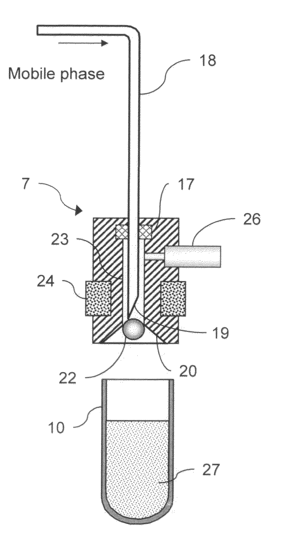
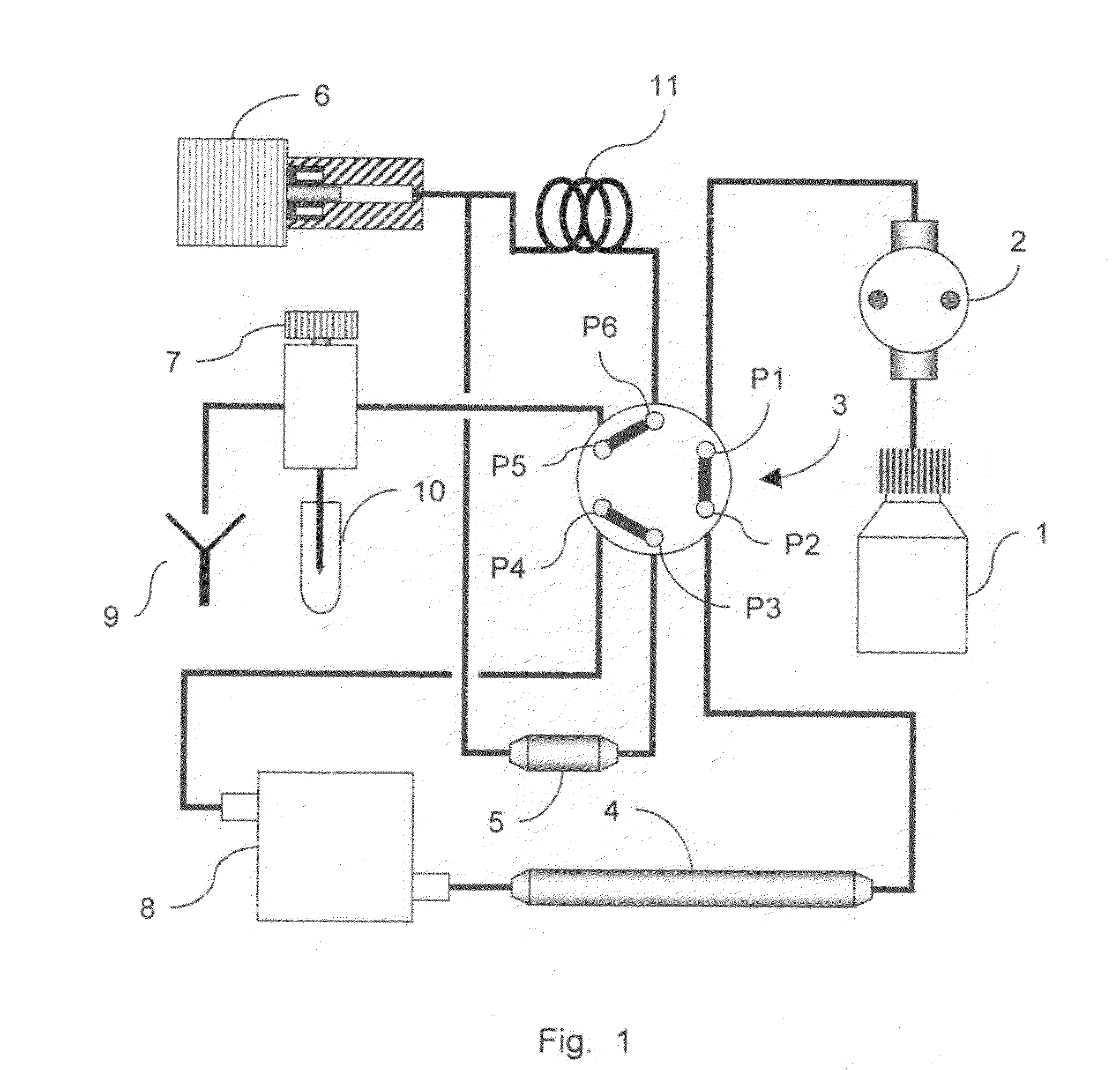
[0014]The disclosed HPLC schematic has a mobile phase vessel 1, a high pressure pump 2, a two position six-port valve 3, a separation column 4, a guard column 5, a syringe 6 for drawing the sample, an injector 7 having a needle 18 to draw the liquid sample from the container 10, a detector 8, a waste outlet 9 for the used mobile phase, and a sample accumulation loop 11.

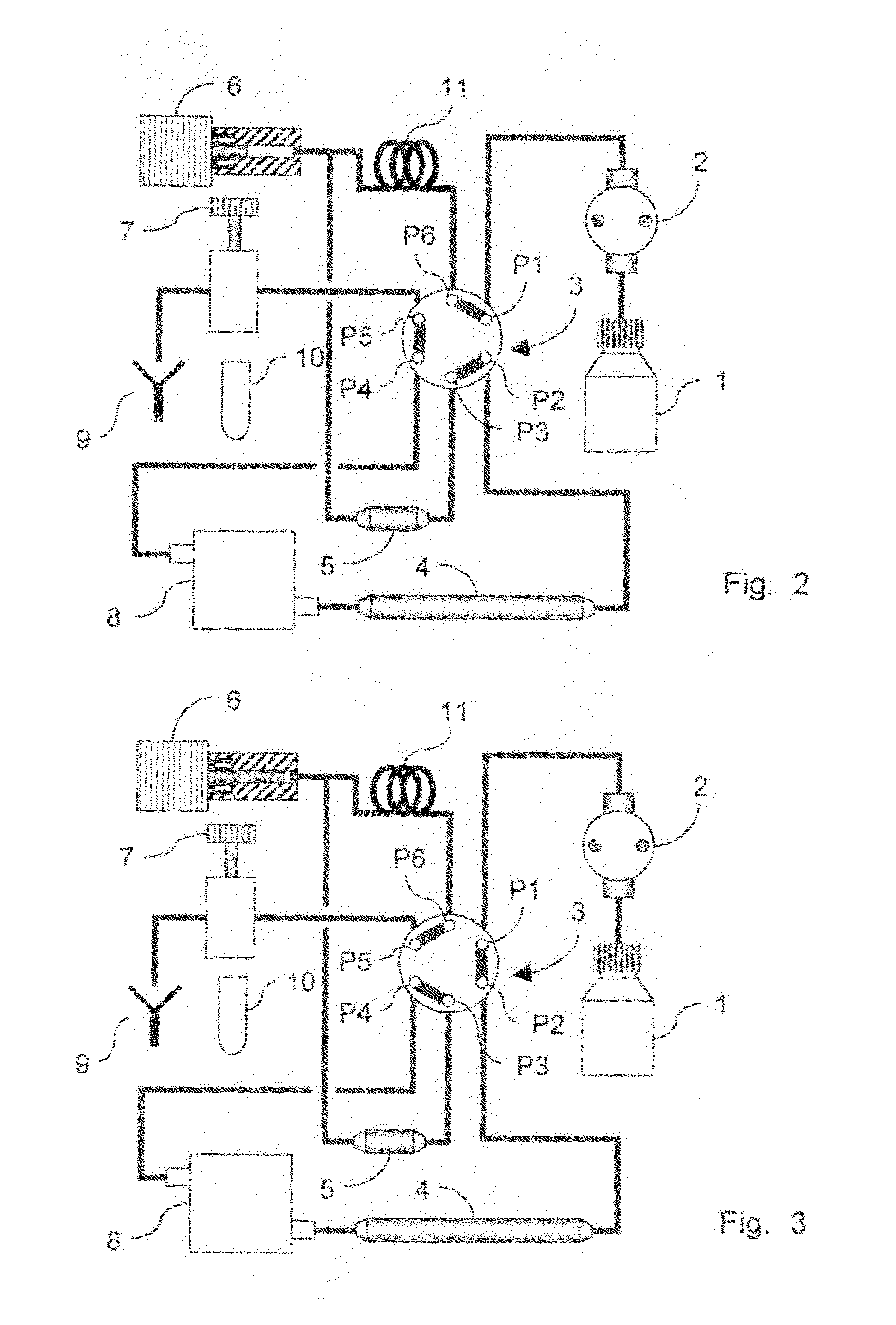
[0015]More specifically, the six-port valve 3 has permanent line connections as follows: port P1 to the outlet of pump 2; port P2 to the inlet of separation column 4; port P3 to one end of guard column 5; port P4 to the outlet of detector 8; port P5 through ports of the injector 7 to waste line 9; and port P6 is via accumulation loop 11 to the syringe 6 and the other end of the guard column 5.

[0016]The valve 3 shifts between two operative positions: FIGS. 1 and 3 illustrating one position where ports P1 and P2, ports P3 and P4, and P5 and P6 are respectively connected; and FIG. 2 illustrating the other operative posit...


PUM

PropertyMeasurementUnit
Dynamic viscosityaaaaaaaaaa

Abstract

The disclosed HPLC flow schematic back-flushes the guard column with mobile phase once every operating cycle, the regular cleaning maintaining its effectiveness and useful life. This mobile phase flow reversal is accomplished by imposing a two position multiple port switching valve between the guard and separation columns. In one valve position, the mobile phase is pumped in one flow direction through both the separation and guard columns, but the switched valve maintains the same flow direction only through the separation column and reverses the mobile phase flow direction through the guard column, for effectively cleaning the guard column. Moreover, the mobile phase back flow is directed over the emptied sample drawing needle for cleaning it to reduce possible sample cross contamination. The improved flow circuits use basically only the typical HPLC system components, except for some insignificant modifications from existing injector designs.

Description

FIELD OF THE INVENTION[0001]This invention relates to high performance liquid chromatography (HPLC), and more specifically to a flow circuit arrangement employed for improved operation of HPLC analysis of complex matrix samples and for improved control of sample carryover.BACKGROUND OF THE INVENTION[0002]HPLC technology is widely used to detect and identify different components contained in a test sample. Typical HPLC instruments use a high pressure pump for forcing a suitable mobile phase, via capillary lines, at a constant flow rate serially through an autosampler, a separation column and a UV or other type detector. The column contains an absorbent selected for the components anticipated to be in the test samples. For instigating a run, a small quantity of the test sample is introduced into the mobile phase by an injector to travel through the separation column. The different sub phase sample components pass through the column at different rates, each thereby becoming substantial...

Claims


Application Information

Patent Timeline
IPC IPC(8): B01D15/40B01D15/22
CPCG01N35/1004G01N30/40
Inventor ZELECHONOK, YURYORLOVSKY, VLADISLAV
Owner SIELC TECH
Why Eureka
Try Eureka