Surface-Mount Inductor and Method of Producing the Same

a technology of inductor and surface mount, which is applied in the direction of transformer/inductance coil/winding/connection, inductance, etc., can solve the problems of increasing cost, difficult to fix the coil only through the end, and the portion between the lead frame and each of the ends of the coil is likely to be separated from each other, etc., to achieve simple structure, simple manner, and low cost

Active Publication Date: 2010-10-14
MURATA MFG CO LTD
View PDF7 Cites 85 Cited by
  • Summary
  • Abstract
  • Description
  • Claims
  • Application Information

AI Technical Summary

Benefits of technology

[0010]As above, in the surface-mount inductor production method of the present invention, a small-sized surface-mount inductor can be obtained in a simple manner. In addition, the coil can be embedded in the molded body while allowing at least portions of the opposite ends of the coil to be fixed at given positions of the molded body

Problems solved by technology

However, the conventional method using a lead frame involves a problem of a large material loss in the lead frame, which becomes a factor causing an increase in cost.
Moreover, even if the ends of the coil are joined to the lead frame by means of resistance welding or the like, the joined portion between the lead frame and each of the ends of the coil is likely to be separated from each other due to a springback phenomenon in the coil.
In this case, if the wire diameter is excessively small, it is difficult to fix the coil only through the ends thereof.
Thus, this method is hardly used t

Method used


Image

  • Surface-Mount Inductor and  Method of Producing the Same
  • Surface-Mount Inductor and  Method of Producing the Same
  • Surface-Mount Inductor and  Method of Producing the Same

Examples


first embodiment

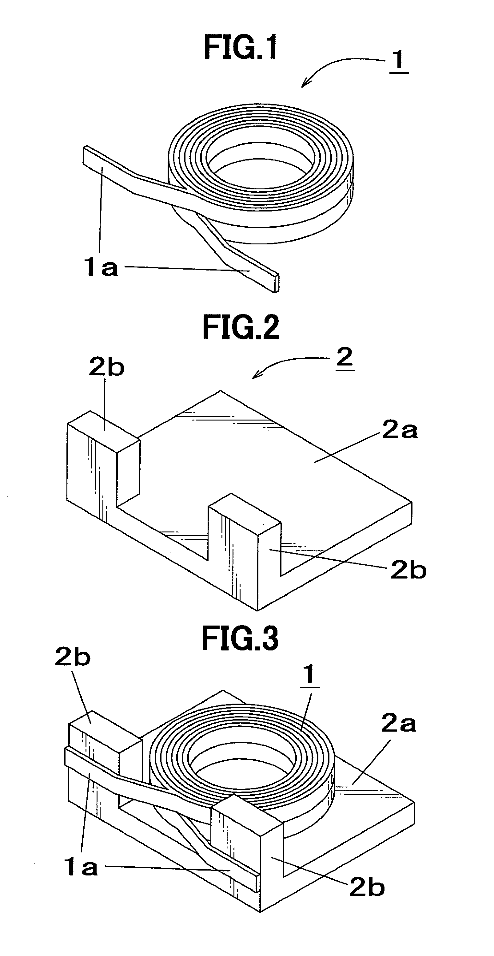
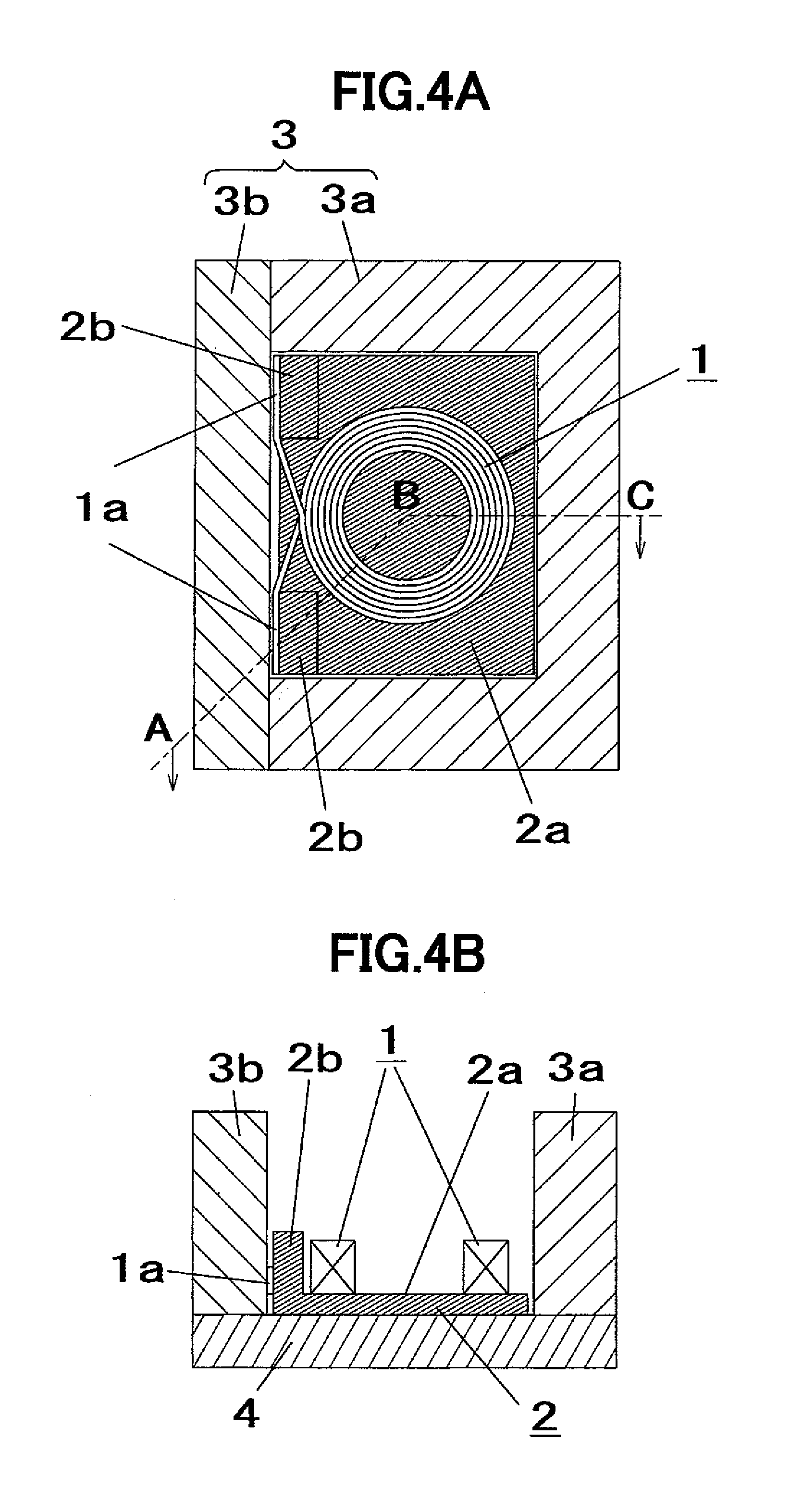
[0027]With reference to FIGS. 1 to 7, a surface-mount inductor production method according to a first embodiment of the present invention will be described. Firstly, an air-core coil for use in the first embodiment will be described. FIG. 1 is a perspective view of the air-core coil for use in the first embodiment. As shown in FIG. 1, the air-core coil 1 for use in the first embodiment is obtained by winding a rectangular (cross-sectionally rectangular-shaped) wire in a two-tiered spiral pattern. The air-core coil 1 is formed to allow each of opposite ends 1a thereof to be located at an outermost position. Further, the air-core coil 1 is formed to allow each of opposite ends 1a to be led out toward the same lateral side.

[0028]Secondly, an encapsulation material for use in the first embodiment will be described. The encapsulation material for use in the first embodiment is a mixture of an iron-based metal magnetic powder and an epoxy resin. A base tablet is formed using this encapsul...

second embodiment

[0035]With reference to FIGS. 8 to 12, a surface-mount inductor production method according to a second embodiment of the present invention will be described. In the second embodiment, the same rectangular wire as that in the first embodiment, and an encapsulation material having the same composition as that of the encapsulation material in the first embodiment are used. Descriptions about a common structure and process to those in the first embodiment will be omitted on a case-by-case basis.

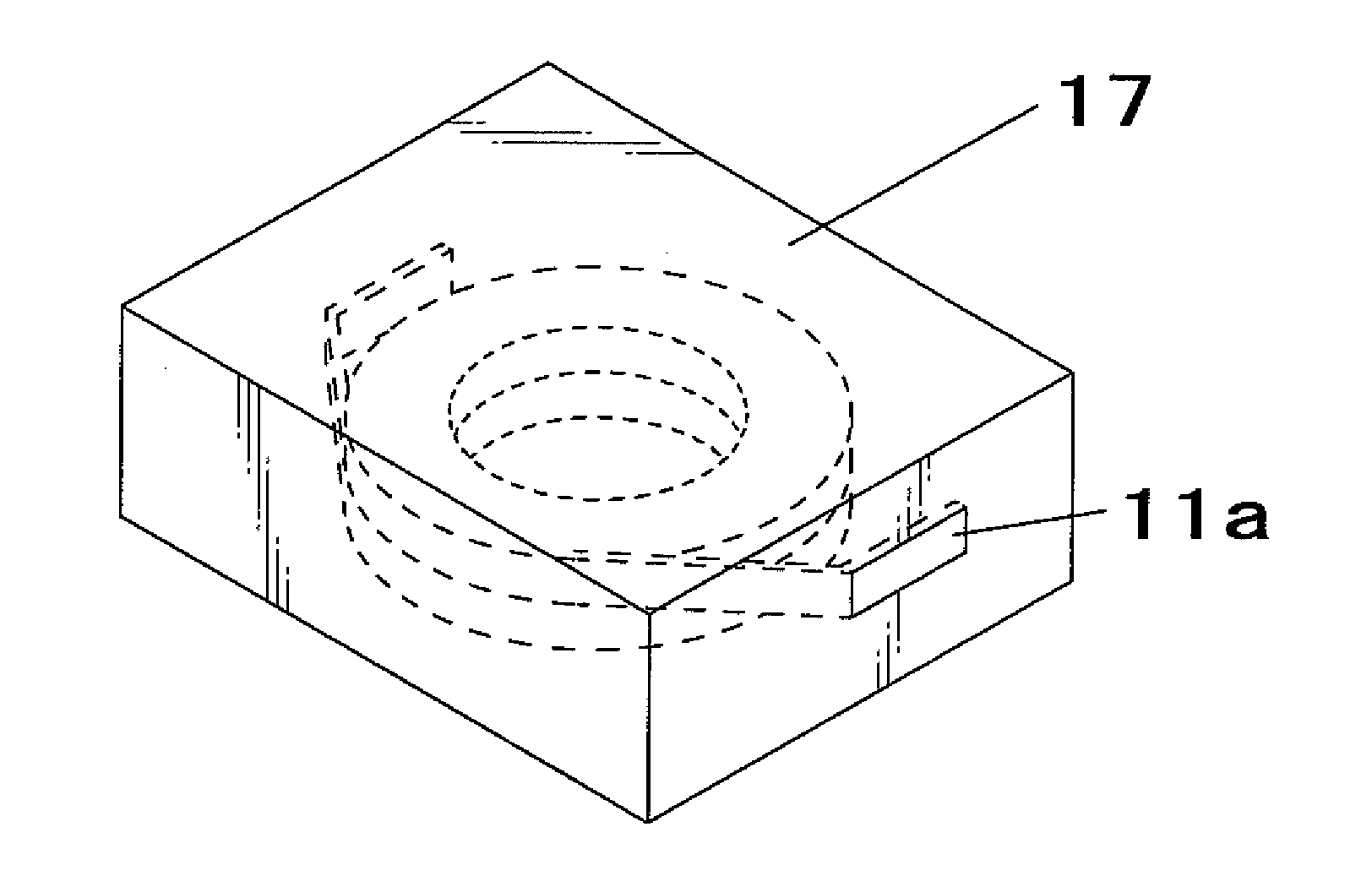
[0036]FIG. 8 is a perspective view for explaining a positional relationship between an air-core coil and a base tablet in the second embodiment. The air-core coil 11 for use in the second embodiment is obtained by winding a rectangular wire in a two-tiered spiral pattern, in the same manner as that in the first embodiment. The air-core coil 11 is formed to allow each of opposite ends 11a thereof to be located at an outermost position. The base tablet 12 for use in the second embodiment is prefor...


PUM

PropertyMeasurementUnit
Magnetismaaaaaaaaaa

Abstract

A method of producing a surface-mount inductor by encapsulating a coil with an encapsulation material containing a resin and a filler using a mold die assembly is provided. In the method, a tablet and a coil are used. The tablet is prepared by preforming the encapsulation material into a shape having a flat plate-shaped portion and a pillar-shaped convex portion on a peripheral thereof. The coil is a wound conductive wire having a cross-section of rectangular-shape. The coil is placed on the tablet to allow both ends of the coil to extend along an outer side surface of the pillar-shaped convex portion of the tablet. The coil and the encapsulation material are integrated together while clamping the both ends of the coil between an inner wall surface of the mold die assembly and the outer side surface of the pillar-shaped convex portion of the tablet, to form a molded body. External electrodes are formed on a surface of or around an outer periphery of the molded body in such a manner that the external electrodes are electrically connected to the both ends of the coil at least a portion of which is exposed to the surface of the molded body.

Description

BACKGROUND OF THE INVENTION[0001]1. Field of the Invention[0002]The present invention relates to a method of producing a surface-mount inductor, and a surface-mount inductor produced by the method.[0003]2. Description of the Background Art[0004]Currently, a surface-mount inductor is widely used which has a structure where a coil is encapsulated by an encapsulation material containing a magnetic powder and a resin. As a conventional technique of producing a surface-mount inductor, there has been known a surface-mount inductor production method using a lead frame, as disclosed, for example, in JP 2003-290992A. In this method, opposite ends of a coil are joined to a lead frame by resistance welding or the like. Then, the entire coil is encapsulated by an encapsulation material to obtain a molded body. A portion of the lead frame exposed from the molded body is subjected to shaping, such as bending, to form an external electrode.[0005]Recent technical innovation in downsizing and functi...

Claims


Application Information

Patent Timeline
IPC IPC(8): H01F27/30B29C39/10
CPCH01F27/292H01F27/327H01F2017/048Y10T29/4913Y10T29/4902Y10T29/49069Y10T29/49146H01F41/005H01F41/127
Inventor SAITO, KOICHISAKAI, CHITOSHI
Owner MURATA MFG CO LTD
Why Eureka
Try Eureka