Light-emitting device and method for fabricating the same

a technology of light-emitting devices and manufacturing methods, applied in the direction of spectral modifiers, refractors, lighting and heating apparatuses, etc., can solve the problems of short service life, low energy conversion efficiency, high energy consumption, etc., and achieve the effect of increasing light concentration and improving the directivity of light beams

Inactive Publication Date: 2010-10-14
AUROTEK CORP
View PDF3 Cites 13 Cited by
  • Summary
  • Abstract
  • Description
  • Claims
  • Application Information

AI Technical Summary

Benefits of technology

[0016]Compared with the prior art, the light-emitting device of the present invention and method for fabricating the same essentially comprises a lens partially coated with a reflective layer so as to enable light beams generated by a light-emitting component to radiate to the outside in a specific direction through reflection of the reflective layer, so as to improve directivity of light beams, increase light concentration, form specific light distribution patterns on an illuminated surface outside the light-emitting device, dispense with secondary optical mechanism, and overcome the above drawbacks of the prior art, that is, scattering light cannot be concentrated and thus lacks directivity.

Problems solved by technology

Since traditional illumination devices have the disadvantages, such as high energy consumption, low energy conversion efficiency, and short service life, more and more products are adopting LED technology for illumination purposes.
However, due to low intensity of LED lighting, chip package techniques have to be used to establish electrical connection and enhance light emitting efficiency and heat dissipating efficiency.
The design of the packaged lens, however, scatters light and makes it impossible to concentrate light beams so as to enhance brightness without being provided with an additional external secondary optical mechanism.
However, the conventional package structure is unfavorable to the performance of a light-emitting component in terms of efficiency of light emission.
Although the conventional package structure changes a path of light emitted and uses a transparent substrate, the transparent substrate is inefficient in heat dissipation.
Heat generated by the light-emitting component is not efficiently dissipated by accumulates at the junction of the light-emitting component and the substrate, resulting in high temperature of the light-emitting component and low efficiency of light emission.
In short, the conventional package structure is unfavorable to enhancement of brightness.

Method used


Image

  • Light-emitting device and method for fabricating the same
  • Light-emitting device and method for fabricating the same
  • Light-emitting device and method for fabricating the same

Examples


Embodiment Construction

[0033]The following illustrative embodiments are provided to illustrate the disclosure of the present invention. Advantages and effects of the present invention can be readily understood by those skilled in the art after reading the disclosure of this specification. The present invention can also be performed or applied by other embodiments. The details of the specification may be changed on the basis of different points and applications, and numerous modifications and variations can be devised without departing from the spirit of the present invention.

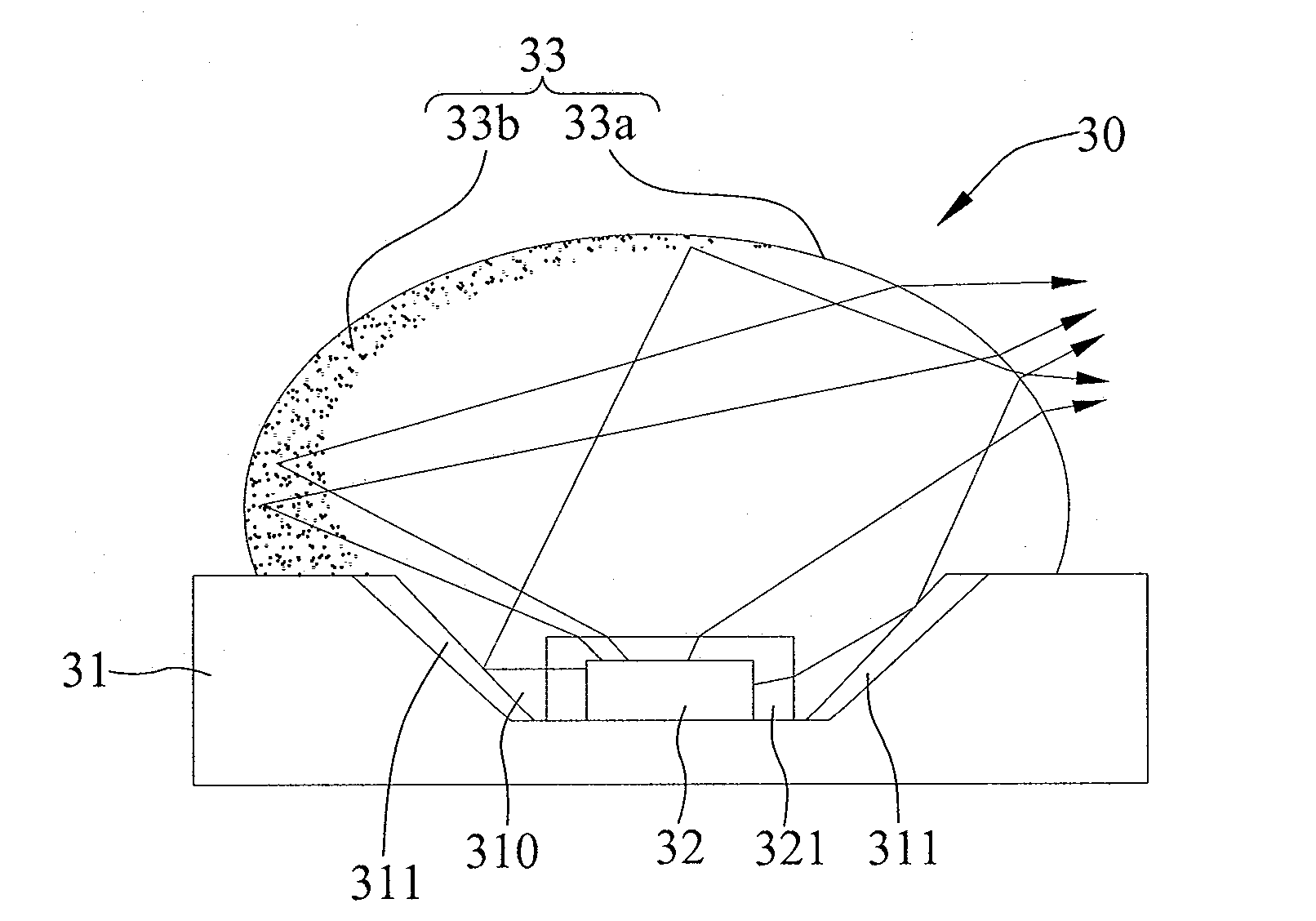
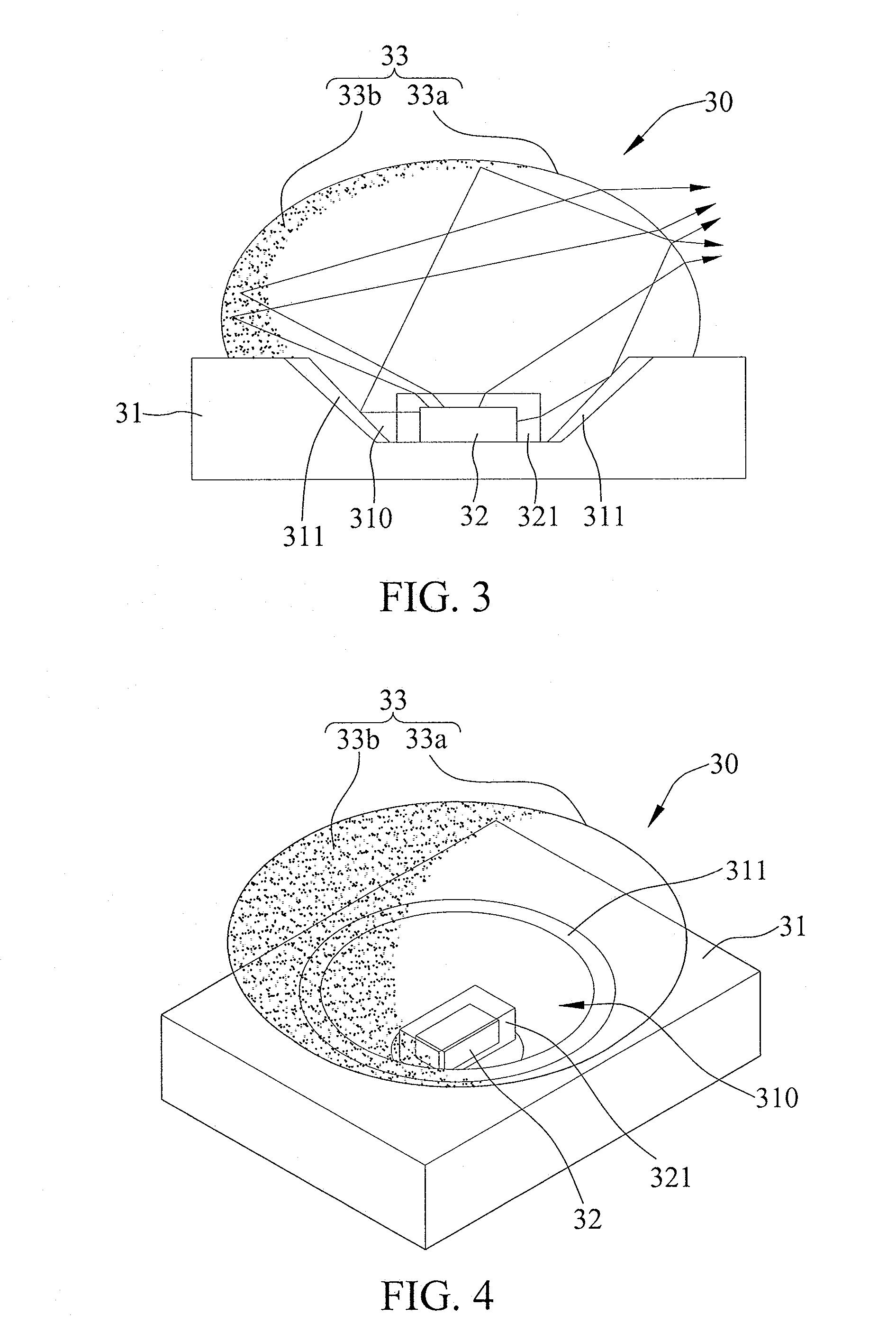
[0034]Referring to FIGS. 3 and 4, which are a schematic view and a perspective diagram of a light-emitting device according to an embodiment of the present invention, respectively, a light-emitting device 30 of the present invention comprises: a substrate 31, a light-emitting component 32 disposed on the substrate 31, a lens 33 covering the light-emitting component 32 disposed on the substrate 31, and a light emission surface 33a defi...


PUM


Abstract

A light-emitting device and a method for fabricating the same are provided. The light-emitting device includes: a substrate; a light-emitting component disposed on the substrate; a lens covering the substrate to hermetically seal the light-emitting component; and a reflective layer formed and a light emission surface defined on the surface of the lens such that light beams generated by the light-emitting component are reflected off the reflective layer, refracted by the light emission surface, and then emitted outward in a specific direction, thereby forming specific light distribution patterns on an illuminated surface outside the light-emitting device.

Description

BACKGROUND OF THE INVENTION[0001]1. Field of the Invention[0002]This invention generally relates to light-emitting devices and methods for fabricating the same, and more particularly, to a light-emitting device that adopts an LED (Light-Emitting Diode) chip to generate a light beam having directivity and method for fabricating the same.[0003]2. Description of Related Art[0004]In general, lighting is provided by artificial light sources or natural light sources. Compared with natural light sources, artificial light sources which are more diverse in their purposes are used in road illumination, billboard illumination, building illumination, residential illumination, stage illumination, medical illumination, internal and external illumination for vehicles, plant cultivation illumination and so on.[0005]Since traditional illumination devices have the disadvantages, such as high energy consumption, low energy conversion efficiency, and short service life, more and more products are adopt...

Claims


Application Information

Patent Timeline
Patent Type & Authority Applications(United States)
IPC IPC(8): F21V9/16F21V7/00H01L33/00
CPCH01L33/58H01L33/60
Inventor SUN, JUI-HUNG
Owner AUROTEK CORP
Why Eureka
Try Eureka