Backlight module

Inactive Publication Date: 2010-10-14
WINTEK CORP
View PDF4 Cites 6 Cited by
  • Summary
  • Abstract
  • Description
  • Claims
  • Application Information

AI Technical Summary

Benefits of technology

[0005]In light of the above-mentioned problem, one object of the invention is to prov

Problems solved by technology

Such deficiency can not be cured

Method used


Image

  • Backlight module
  • Backlight module
  • Backlight module

Examples


Embodiment Construction

[0017]The above and other technical content, characteristics, and effects of the invention will be described in details with reference to the drawings. For clarity, the wording related to direction, such as up, down, left, right, front, back, etc., is merely used to describe the direction with respect to the drawings but does not limit the scope of the invention.

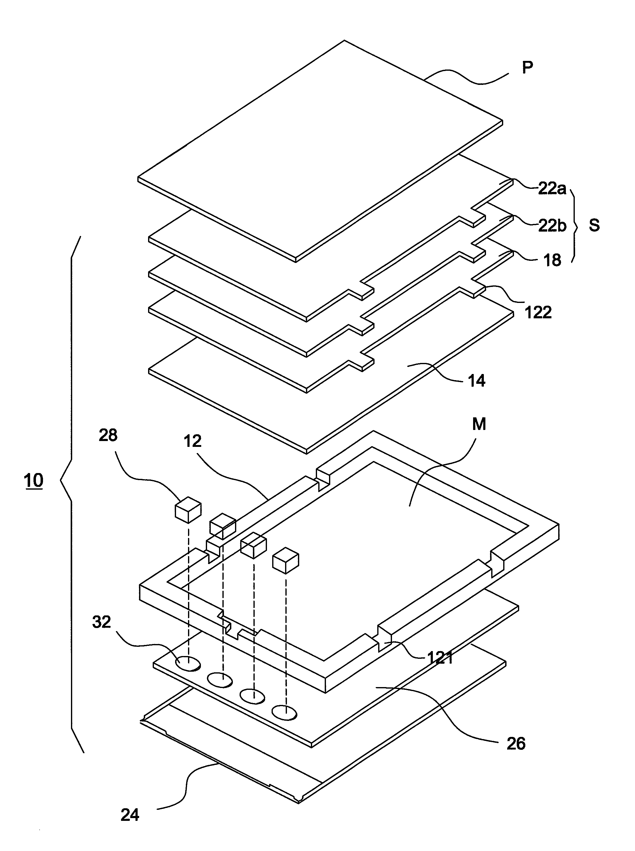
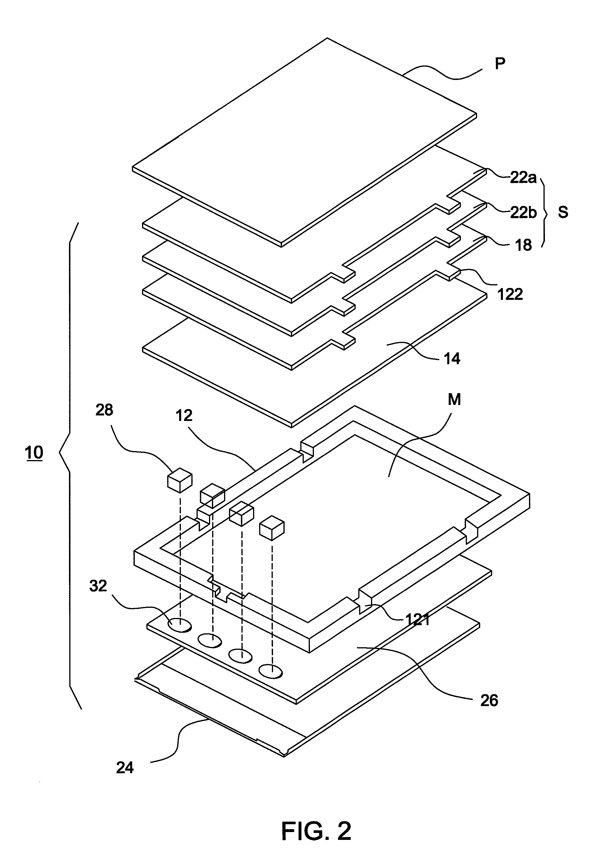
[0018]FIG. 2 shows an exploded diagram of a backlight module according to an embodiment of the invention. Referring to FIG. 2, a liquid crystal panel P is on the top of the backlight module 10. In one embodiment, the backlight module 10 includes a frame 12, a light guide plate 14, and an optical film set S. The optical film set S may include a light diffusion film 18, an X-axis prismatic brightness enhancement film (BEF) 22a, and a Y-axis prismatic BEF 22b. The frame 12 defines an accommodation space M and has multiple notches 121. Each optical film has a protrusion 122 formed at a position corresponding to a notch 121. Henc...


PUM


Abstract

A backlight module includes a frame, a reflective sheet, a light guide plate, a light source, and an optical film set. The frame defines an accommodation space, and the reflective sheet is disposed in the accommodation space. The light guide plate is disposed in the accommodation space and on one surface of the reflective sheet. The optical film set is disposed one side of the light guide plate opposite the reflective sheet. The reflective sheet is hollowed out at a position overlapping the light source to form at least one opening so as to reduce light halos.

Description

BACKGROUND OF THE INVENTION[0001](a) Field of the Invention[0002]The invention relates to a backlight module having reduced light halos and improved luminous uniformity.[0003](b) Description of the Related Art[0004]FIG. 1 shows a schematic diagram illustrating a conventional backlight module. Referring to FIG. 1, the backlight module 100 under a liquid crystal panel 102 includes a top brightness enhancement film (BEF) 104, a bottom brightness enhancement film 106, a light diffusion film 108, a light guide plate 110 and a reflective sheet 112. Since the current trend is towards more light and thin in the design of a liquid crystal display, the distance between an active display area (AA area) and a light source 114 in the backlight module 100 becomes shorter and shorter. Hence, in case such distance is smaller than 3 mm, light halos are formed on the liquid crystal panel 102 to seriously reduce luminous uniformity. Such deficiency can not be cured by spreading light-diffusing dots. T...

Claims


Application Information

Patent Timeline
IPC IPC(8): F21V7/04
CPCG02B6/0088G02B6/0055
Inventor YE, ZHI-TINGYU, CHANG-WEIYANG, NIEN-YINGHUANG, KUO-JUISHIH, YING-CHENGLEE, HSIU-PING
Owner WINTEK CORP
Why Eureka
Try Eureka